Shore-based berthing system, method and equipment based on radar capture and laser tracking

A technology of laser tracking and radar capture, applied in radio wave measurement systems, radio wave reflection/re-radiation, utilization of re-radiation, etc., can solve problems such as narrow field of view, little practical value, and inability to reflect ship contour features

Pending Publication Date: 2021-09-28
武汉理工港航科技研究院有限公司
View PDF5 Cites 2 Cited by
  • Summary
  • Abstract
  • Description
  • Claims
  • Application Information

AI Technical Summary

Problems solved by technology

[0003] The price of thermal imaging is too high, and the field of view is very narrow. If you want to obtain the information of berthing ships several kilometers away, the operation is complicated and the effect is not very good; LiDAR can only detect objects within 100 meters. Said that the practical value is not great, and two (corresponding to the bow and stern) can be obtained, and the cost performance is not high; the field of view of the thermal imaging lens is very narrow, and the thermal imaging lens is already occupied within 600 meters of the ship from the shore, which cannot reflect the outline of the ship Features, unable to accurately obtain bow and stern information, ship type information, which brings great invariance to the berthing of ships, and the overall cost is high

Method used


Image

  • Shore-based berthing system, method and equipment based on radar capture and laser tracking
  • Shore-based berthing system, method and equipment based on radar capture and laser tracking
  • Shore-based berthing system, method and equipment based on radar capture and laser tracking

Examples


Embodiment Construction

[0060] The principles and features of the present invention will be described below with reference to the accompanying drawings, and the exemplary examples are intended to be construed as they are intended to limit the scope of the invention.

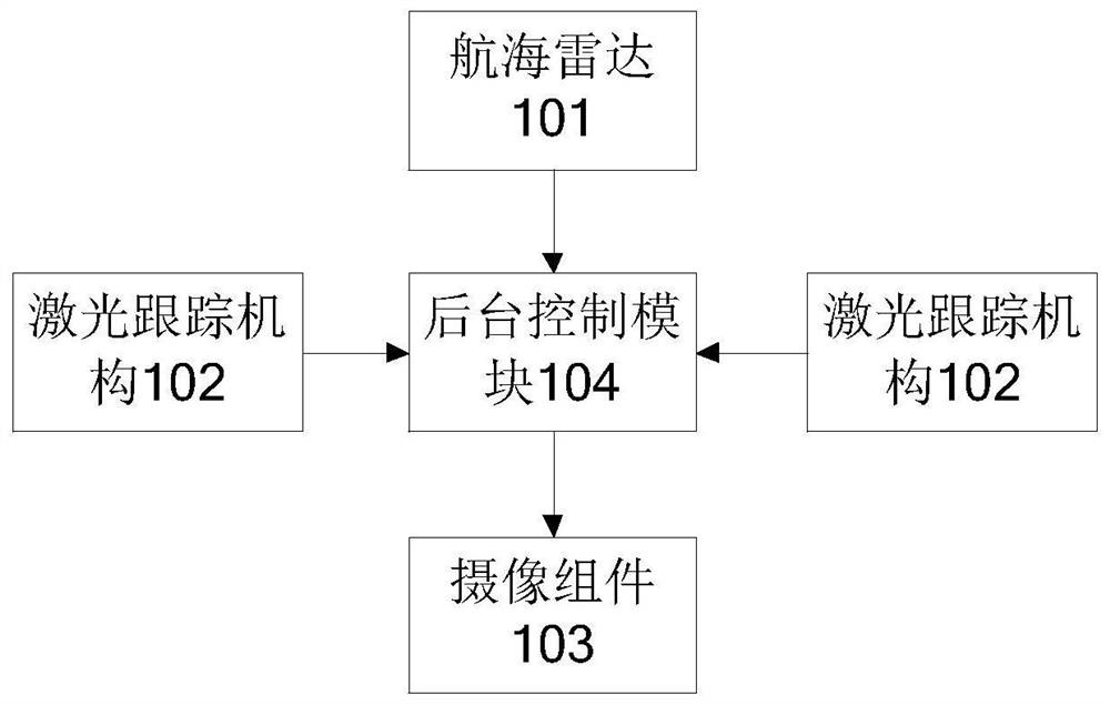
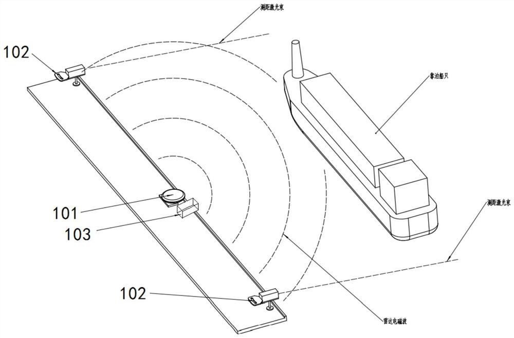
[0061] like figure 1 with figure 2 As shown, a shore-based berthing system based on radar capture and laser tracking, including navigation radar 101, two laser tracking mechanisms 102, imaging assembly 103, and background control module 104 ( figure 2 Not shown), the navigation radar 101, the laser tracking mechanism 102 and the imaging assembly 103 are all set at the shore base berth, and the two of the laser tracking mechanisms 102 are respectively disposed in the navigation radar 101 and the imaging assembly 103. between;

[0062] The navigation radar 101 is used to scan the ship within the waterway and obtain the orientation information of the ship and the distance information of the ship and the shore.

[0063] The background control m...


PUM


Abstract

The invention relates to a shore-based berthing system, method and equipment based on radar capture and laser tracking, and the method comprises the step that a marine radar scans a ship in a navigation channel, obtains the azimuth information of the ship and the distance information between the ship and a shore, and screens out a target ship which is being berthed; according to the distance between the target ship and the shore base, a laser tracking mechanism is scheduled to track and scan the distances between the two ends of the target ship and the shore base, and berthing information is generated; meanwhile, a camera shooting assembly is controlled to capture the target ship, ship image information is obtained, image processing is carried out, and ship type information of the target ship is determined. The azimuth information of ships in the navigation channel and the distance between the ships and a shore base are monitored through the marine radar in the whole course, target ships are screened out, a background dispatch controls a laser tracking mechanism to dynamically track and controls a camera shooting assembly to obtain ship image information, and then bow and stern information and ship type information are determined; omnibearing and multi-level monitoring and tracking of the whole process are realized, and automatic tracking is realized.

Description

Technical field [0001] The present invention relates to berthing and shore-based technology, and particularly relates to shore docking system based radar and laser tracking method and apparatus. Background technique [0002] In the course of the ship to dock, the need for dynamic real-time monitoring and tracking of ships, such as location, distance from shore and posture and so on. The prior art, the main instrument is the use of berthing, berthing process through comprehensive coverage of the thermal imaging and laser radar, capable of berthing process information effectively capture the ship, in the Nansha three piers, docks WIT three trials, with good results , but there are great deficiencies: [0003] Thermal image price is too high, very narrow field of view, want to get information about a few kilometers away berthing vessel, complicated operation, is not very good; lidar can detect objects within 100 meters, for ocean-going vessels of this size to the above objects 200 H...

Claims


Application Information

Patent Timeline
IPC IPC(8): G01S13/86G01S13/937
CPCG01S13/86G01S13/867G01S13/937Y02A10/40
Inventor 徐承军董熙晨朱泽
Owner 武汉理工港航科技研究院有限公司
Why Eureka
Try Eureka