
Ball flow positioning and tracking experimental device and method

An experimental device, positioning and tracking technology, applied in the field of nuclear engineering, can solve the problems of heavy workload, high cost, and the success rate and accuracy of experiments need to be improved, and achieve the effect of rapid positioning and tracking

Active Publication Date: 2021-09-28
HUANENG SHANDONG SHIDAO BAY NUCLEAR POWER CO LTD
View PDF10 Cites 0 Cited by
  • Summary
  • Abstract
  • Description
  • Claims
  • Application Information

AI Technical Summary

Problems solved by technology

However, the traditional phenomenology method manually observes and records the ball flow movement by setting marker balls. Although the preparation work is simple, the workload is heavy, and only a small number of balls can be observed at the same time, and human errors are prone to occur.
The advantage of the radioactive tracer method is that the experiment can be carried out directly on the 3D model, which can more realistically simulate the actual core structure, and the acquisition of the ball flow trajectory is more objective and reliable. However, the disadvantage of this method is that in most cases, every This experiment can only track the movement of one radiation ball, and the motion of the ball is required to be discontinuous. If you want to obtain multiple motion trajectories, you need to manually adjust the initial placement position of the radiation ball. The requirements for the experimental conditions and analysis algorithms are very strict. Strict, the success rate and accuracy of the experiment need to be improved
In addition, the equipment cost of the radioactive tracer method is expensive, and the experiment cost is relatively high.
The X-ray projection method can obtain the translational and rotational displacement of the ball at the same time. The experimental results can be used to verify the simulation results of the DEM ball flow motion, and provide an effective method for studying the distribution and residence time of the pebble bed reactor fuel balls. It has defects such as low efficiency, low efficiency, and difficulty in tracking the movement of the ball during the entire printing process. It pays more attention to the displacement of a large number of balls in a short distance and in a short time.

Method used


Image

  • Ball flow positioning and tracking experimental device and method
  • Ball flow positioning and tracking experimental device and method

Examples


Embodiment Construction

[0036] In order to enable those skilled in the art to better understand the technical solutions of the present invention, the present invention will be further described in detail below in conjunction with the accompanying drawings and specific embodiments.

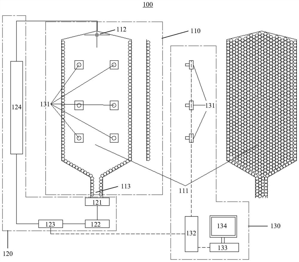
[0037] In one aspect of the present invention, as figure 1 As shown, an experimental device 100 for positioning and tracking a ball flow is provided. The experimental device 100 includes a two-dimensional core stand 110 , an external circulation system 120 and a computing system 130 . The two-dimensional core stand 110 is provided with an accommodating chamber 111 , so that several graphite spheres can be tiled in a single layer in the accommodating chamber 111 . The external circulation system 120 communicates with the containing chamber 111 , so that several graphite balls circulate in the containing chamber 111 . The computing system 130 is electrically connected with the external circulation system 120, so that when ...


PUM


Abstract

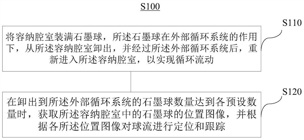
The invention relates to a ball flow positioning and tracking experimental device and method. The experimental device comprises a two-dimensional reactor core rack, an external circulation system and a calculation system; the two-dimensional reactor core rack is provided with an accommodating chamber, so that a plurality of graphite nodules can be flatly laid in the accommodating chamber in a single layer; the external circulation system communicates with the accommodating chamber, so that the plurality of graphite nodules circularly flow in the accommodating chamber; and the calculation system is electrically connected with the external circulation system so as to obtain position images of all the graphite nodules in the containing cavity when the number of the graphite nodules discharged from the containing cavity reaches the preset number, and positioning and tracking of the nodule flow are achieved according to all the position images. According to the device and method, the absolute positions of all graphite nodules in the experimental device at any moment can be rapidly and accurately detected without special identification, the ball flow tracks of all graphite nodules in the experimental device are tracked in the whole course and full range, and the graphite nodules in the two-dimensional ball flow model are rapidly positioned and tracked in the full range and with high precision.

Description

technical field [0001] The invention relates to the technical field of nuclear engineering, in particular to an experimental device and method for ball flow positioning and tracking. Background technique [0002] The high-temperature gas-cooled reactor adopts pebble bed core and non-stop refueling technology. The fuel balls pass through the core multiple times, that is, the fuel balls are loaded from the top of the core, flow down through the core under the action of gravity, fission to generate heat, and then unload the core through a special unloading device, and pass through the burnup measurement device After measuring the burnup, the fuel balls that have not reached the unloading burnup limit are returned to the core through the fuel loading and unloading system, and fission again to generate heat. The fuel balls that have passed through the core fission many times and reached the unloading burnup are unloaded as spent fuel and put into special spent fuel tanks. Thus,...

Claims


Application Information

Patent Timeline
IPC IPC(8): G21C17/00
CPCG21C17/001Y02E30/30
Inventor 程从礼
Owner HUANENG SHANDONG SHIDAO BAY NUCLEAR POWER CO LTD
Learn More