Enameled wire

A technology of enameled wire and fixture, applied in the field of enameled wire, can solve the problems of easy deformation, deformation resistance and drop of insulating film, and achieve the effect of excellent deformation resistance

Pending Publication Date: 2021-09-28
株式会社博迈立铖
View PDF1 Cites 0 Cited by
  • Summary
  • Abstract
  • Description
  • Claims
  • Application Information

AI Technical Summary

Problems solved by technology

[0007] However, if there are voids in the insulating coating, there is a problem that the insulating coating is easily deformed (resistance to deformation decreases).

Method used


Image

  • Enameled wire
  • Enameled wire
  • Enameled wire

Examples


Embodiment approach

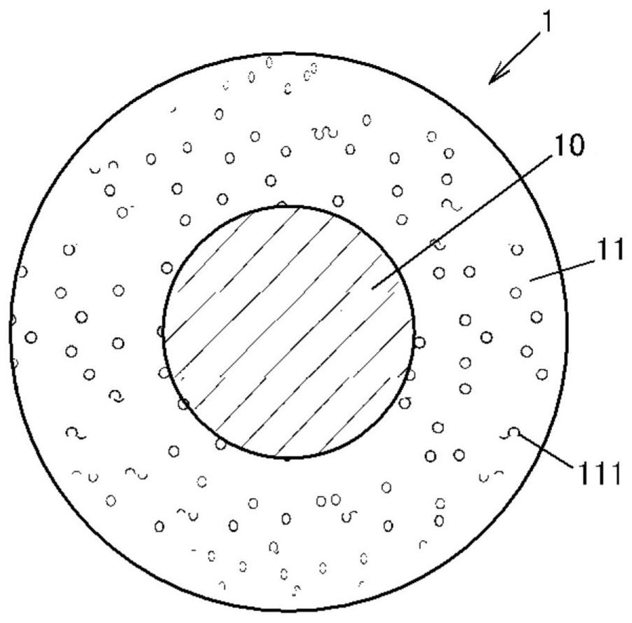
[0024] Fig. 1(a) is a sectional view perpendicular to the longitudinal direction of the enameled wire 1 according to the embodiment of the present invention. The enameled wire 1 includes a conductor 10 and an insulating film 11 provided around the conductor 10 and having a hole 111, and its deformation rate is less than 10%. In addition, the deformation|transformation rate is mentioned later.

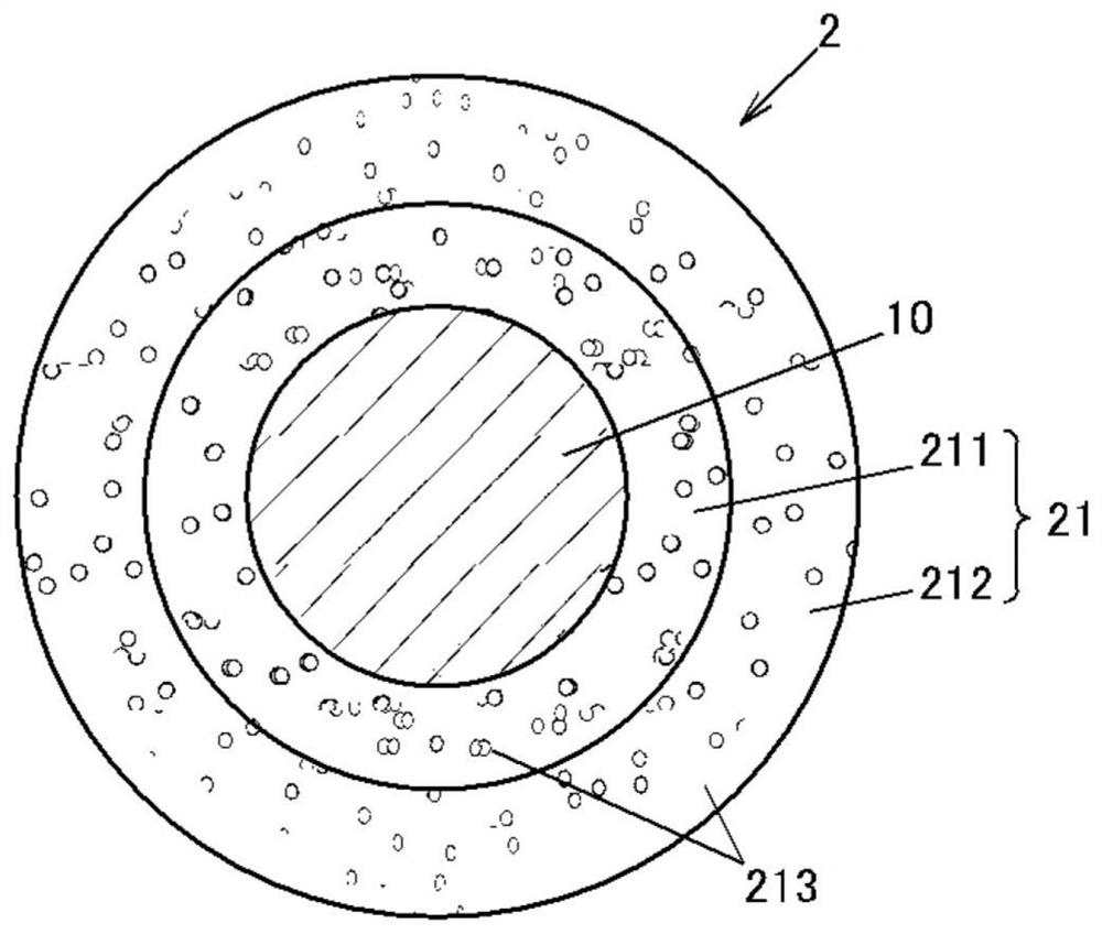
[0025] The conductor 10 is a linear metal wire made of conductive material such as copper or copper alloy, aluminum or aluminum alloy, for example, a copper wire made of oxygen-free copper or low-oxygen copper. In addition, the structure of the conductor 10 is not limited to this, For example, the conductor 10 may use the wire which plated metal, such as nickel, on the outer periphery of a metal wire. The conductor 10 shown in FIG. 1( a ) and FIG. 1( b ) has a circular cross-sectional shape perpendicular to the longitudinal direction, but is not limited thereto, and may be, for example...


PUM

PropertyMeasurementUnit
Thicknessaaaaaaaaaa
Particle sizeaaaaaaaaaa

Abstract

The present invention provides an enameled wire having an insulating film containing pores on a conductor and having excellent deformation resistance. Provide enameled wires (1), (2), which are equipped with a conductor (10) and insulating coatings (11), (21) with holes (111), (213) around the conductor (10), and the deformation rate is lower than 10%. The deformation rate is calculated by the equation of (the second displacement-the first displacement)*100 / (the film thickness of the aforementioned insulating coating*2).

Description

technical field [0001] The present invention relates to enameled wires. Background technique [0002] Conventionally, there is known an insulated wire including an insulating coating made of polyimide having voids on a conductor in order to suppress the occurrence of partial discharge (for example, refer to Patent Document 1). The relative permittivity of air is lower than that of polyimide. Therefore, the insulating film with voids has a lower relative permittivity than the insulating film without voids, and can effectively suppress partial discharge of insulated wires. In the insulated wire described in Patent Document 1, the porosity of the insulating coating is set within a wide range of, for example, 5 vol % or more and 80 vol % or less. [0003] prior art literature [0004] patent documents [0005] Patent Document 1: Japanese Patent Laid-Open No. 2018-170261 Contents of the invention [0006] The problem to be solved by the invention [0007] However, if voids...

Claims


Application Information

Patent Timeline
IPC IPC(8): H01B7/02
CPCH01B7/02
Inventor 西甫牛渡刚真本田祐树安藤郁美
Owner 株式会社博迈立铖
Why Eureka
Try Eureka