

A heat treatment method for improving weld performance after electron beam welding
A heat treatment method and electron beam welding technology, applied in the field of electron beam welding, can solve problems such as poor mechanical properties and weld performance.
- Summary
- Abstract
- Description
- Claims
- Application Information
AI Technical Summary
Problems solved by technology
Method used
Image

Examples
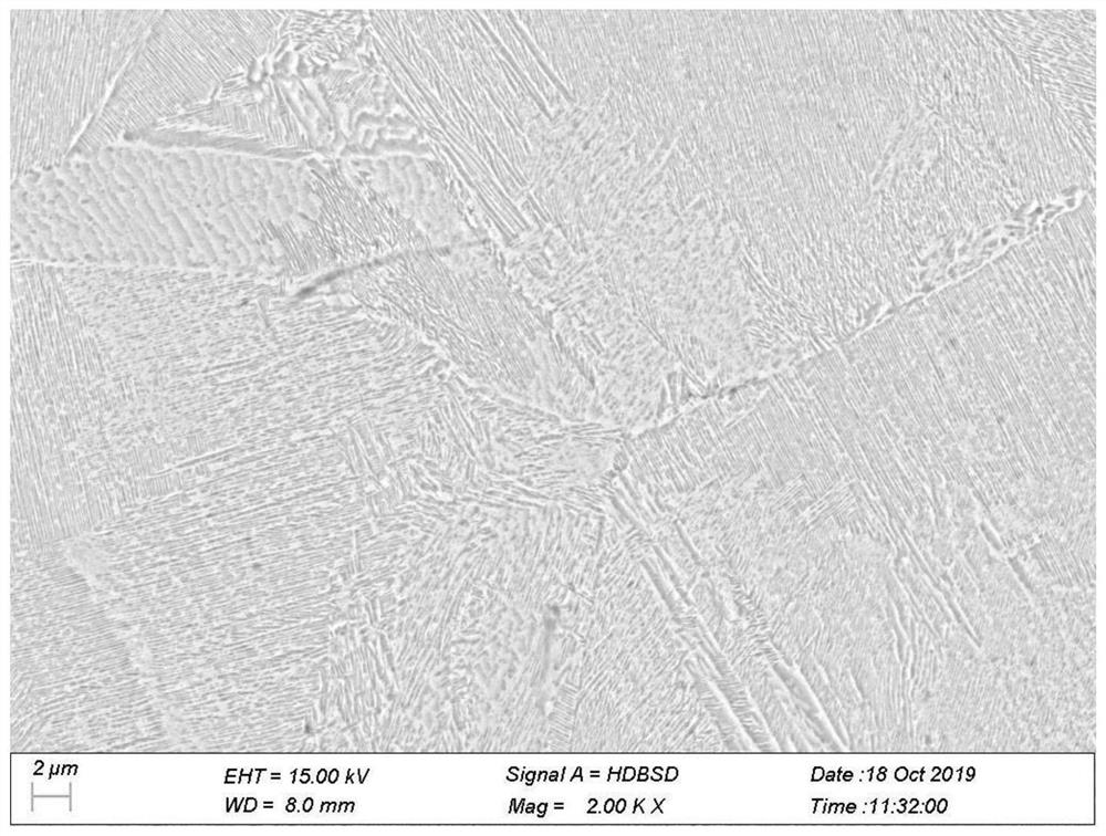
Embodiment 1
[0037] S1. First, ultrasonically clean the parts and test rods with water-based cleaning agent and dry them, and the drying temperature is less than 120 °C.
[0038] S2. Place the parts and test bars on the tray of the vacuum heat treatment furnace (the furnace temperature is less than or equal to 50°C). When the parts are put into the furnace, two load thermocouples are loaded on the parts, and one is placed in the part with the highest temperature. One is placed at the lowest temperature part of the part to accurately monitor temperature changes.
[0039] S3. Evacuate the furnace to make the pressure ≤ 0.13Pa, and start heating.
[0040] S4. The parts are heated up to 500°C at a rate of 15°C, without heat preservation, the parts can reach the set temperature, and then the parts are heated to 850°C at a rate of 8°C, kept for 3 hours, and then cooled with the furnace.
[0041] S5. Cool the parts to below 80°C, and air-cool the parts.
[0042] S6. Test the mechanical properti...
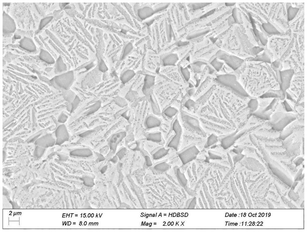
Embodiment 2
[0047] S1. First, ultrasonically clean the parts and test rods with water-based cleaning agent and dry them, and the drying temperature is less than 120°C.
[0048] S2. Place the parts and test bars on the tray of the vacuum heat treatment furnace (the furnace temperature is less than or equal to 50°C). When the parts are put into the furnace, two load thermocouples are loaded on the parts, and one is placed in the part with the highest temperature. One is placed at the lowest temperature part of the part to accurately monitor temperature changes.
[0049] S3. Evacuate the furnace to make the pressure ≤ 0.13Pa, and start heating.
[0050] S4. The parts are heated up to 400°C at a rate of 14°C, without heat preservation, the parts can reach the set temperature, and then the parts are heated to 800°C at a rate of 6°C, kept for 1 hour, and then cooled with the furnace.
[0051] S5. Cool the parts to below 80°C, and air-cool the parts.
[0052] S6. Test the mechanical properties a...
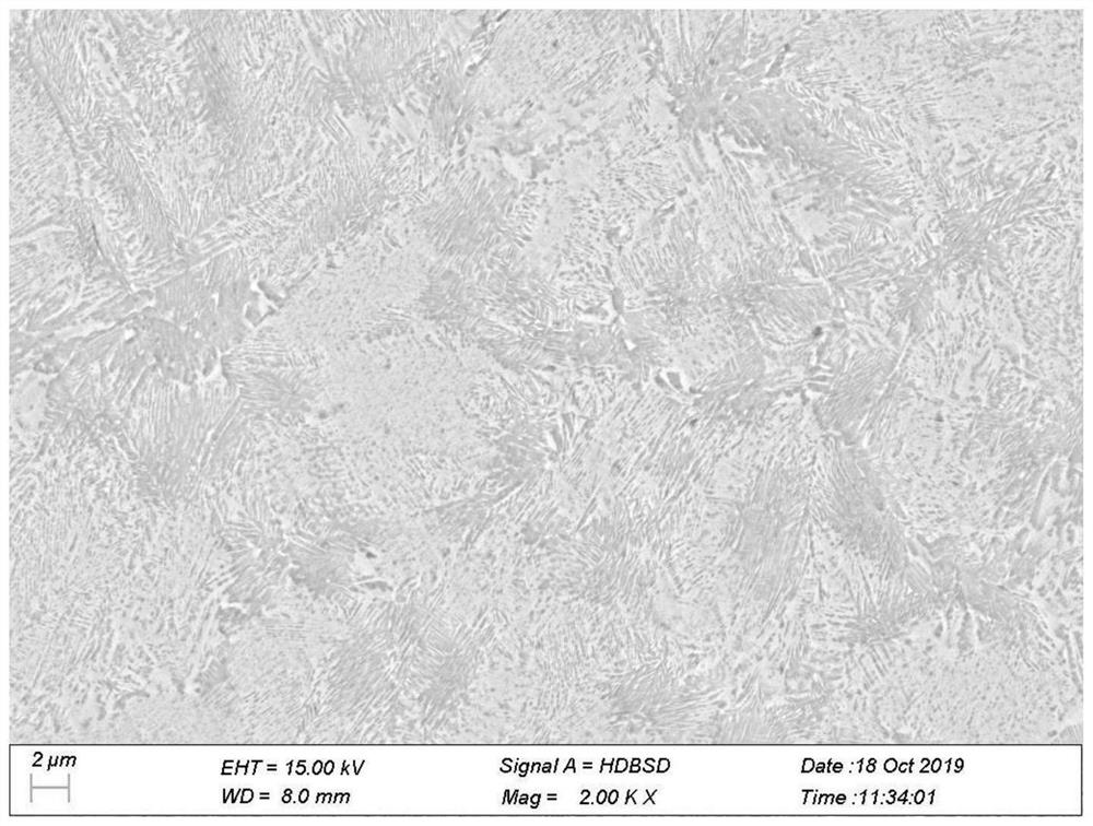
Embodiment 3
[0054] S1. First, ultrasonically clean the parts and test rods with water-based cleaning agent and dry them, and the drying temperature is less than 120 °C.
[0055] S2. Place the parts and test bars on the tray of the vacuum heat treatment furnace (the furnace temperature is less than or equal to 50°C). When the parts are put into the furnace, two load thermocouples are loaded on the parts, and one is placed in the part with the highest temperature. One is placed at the lowest temperature part of the part to accurately monitor temperature changes.
[0056] S3. Evacuate the furnace to make the pressure ≤ 0.13Pa, and start heating.
[0057] S4. The parts are heated up to 600°C at a rate of 13°C without heat preservation. The parts can reach the set temperature. Then, the parts are heated to 750°C at a rate of 7°C, kept for 2 hours, and then cooled with the furnace.
[0058] S5. Cool the parts to below 80°C, and air-cool the parts.
PUM
| Property | Measurement | Unit |
|---|---|---|
| thickness | aaaaa | aaaaa |
Abstract
Description
Claims
Application Information