River sluice for water conservancy project

A technology for water conservancy projects and barrages, applied in water conservancy projects, sea area projects, coastline protection, etc., can solve problems such as water pollution, simple waterproof gate structure, and damage to the balance of water and sand in the river bed, so as to achieve cleanliness and sanitation and save manpower Improvement of material resources and river water quality

Inactive Publication Date: 2021-10-01
李理春
View PDF0 Cites 0 Cited by
  • Summary
  • Abstract
  • Description
  • Claims
  • Application Information

AI Technical Summary

Problems solved by technology

[0006] Aiming at the deficiencies of the prior art, the present invention provides a river sluice for water conservancy projects, which has the advantages of automatically crushing silt and gravel, adapting to the water level and automatically collecting water surface garbage, and solves the problem that the river sluice is responsible for discharging silt and sand. When the silt and gravel at the bottom accumulate too much, the water flow cannot wash away the silt and gravel, which will further destroy the water-sand balance of the river bed. The existing method of processing the accumulation of silt and gravel requires a lot of manpower and material resources , and the traditional structure of the waterproof sluice is simple in structure and single in function. In recent years, in order to increase the needs of urban greening and tourism development, there are dead leaves and domestic garbage floating in urban rivers, which are easy to cause water pollution. The existing barrages cannot control the water flow. The floating dead leaves and domestic garbage in the water are intercepted and collected, and the garbage collection mechanism cannot be automatically adjusted according to the change of the water level, so that the garbage is directly discharged into the downstream water flow, which will further pollute the river along the way.

Method used


Image

  • River sluice for water conservancy project
  • River sluice for water conservancy project
  • River sluice for water conservancy project

Examples


Embodiment Construction

[0027] The following will clearly and completely describe the technical solutions in the embodiments of the present invention with reference to the accompanying drawings in the embodiments of the present invention. Obviously, the described embodiments are only some, not all, embodiments of the present invention. Based on the embodiments of the present invention, all other embodiments obtained by persons of ordinary skill in the art without making creative efforts belong to the protection scope of the present invention.

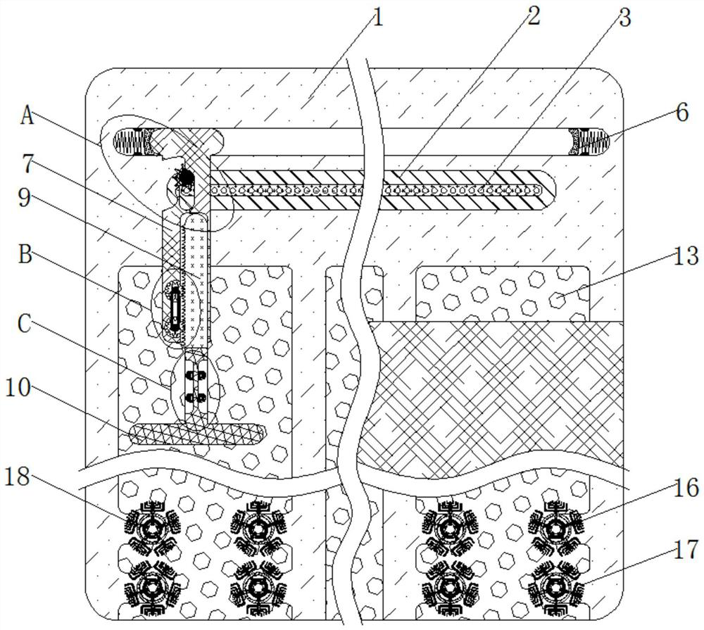
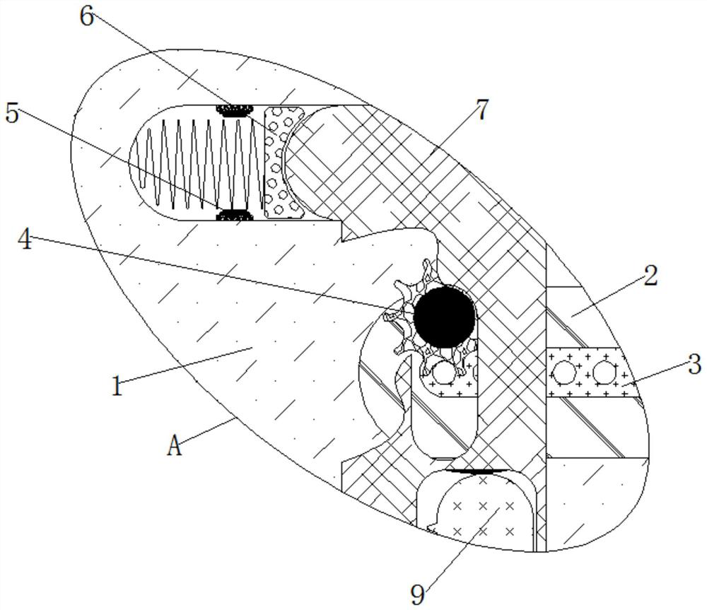
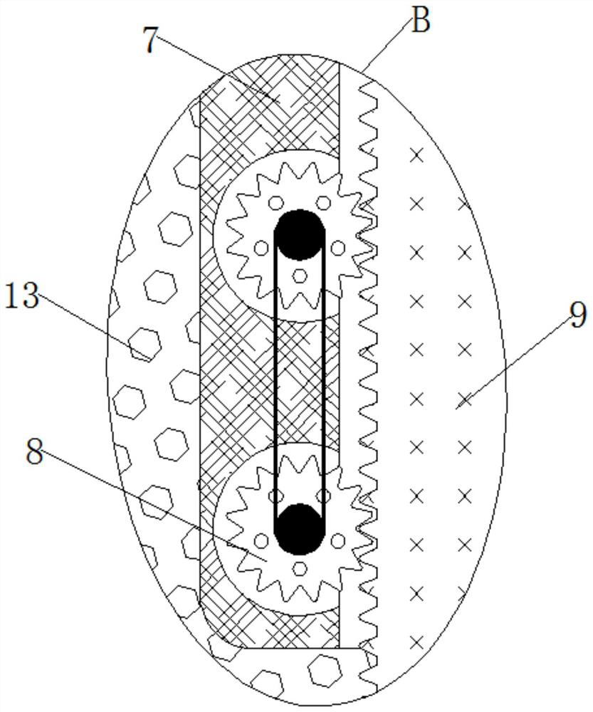
[0028] see Figure 1-5 , a barrage for water conservancy projects, comprising a fixed dam 1, the inside of the fixed dam 1 is fixedly connected with a movable groove 2, the outside of the movable groove 2 is fixedly connected with a rack 3, and the outside of the rack 3 is meshed with an engagement ring 4, The inside of the fixed dam 1 is fixedly connected with a piezoelectric ceramic 5, the inside of the fixed dam 1 is slidably connected with a trigger block ...


PUM


Abstract

The invention relates to the technical field of river sluices, and discloses a river sluice for a water conservancy project. The river sluice comprises a fixed dam; a movable groove is fixedly connected to the interior of the fixed dam; a rack is fixedly connected to the exterior of the movable groove; an engagement ring is engaged to the exterior of the rack; piezoelectric ceramics are fixedly connected to the interior of the fixed dam; the interior of the fixed dam is slidably connected with a trigger block; the interior of the fixed dam is slidably connected with a movable rod; the interior of the movable rod is rotatably connected with a lifting wheel; and the exterior of the lifting wheel is engaged with a toothed bar. Through mutual cooperative use of the fixed dam, the movable groove, the rack, the engagement ring, the piezoelectric ceramics, the trigger block, the movable rod, the lifting wheel, the toothed bar, a filter plate, a direct illuminating lamp and a photosensitive assembly, dead leaves and household garbage floating on a river surface do not need to be manually fished; through automatic operation of the mechanisms, the effects of self-adaption to the water level and automatic collection of the garbage on a water surface can be achieved; and the water quality of a river channel is improved, and cleanness and sanitation of a city are guaranteed.

Description

technical field [0001] The invention relates to the technical field of barrages, in particular to a barrage for water conservancy projects. Background technique [0002] Barrage sluice is a sluice used to adjust the upstream water level and control the discharge flow on the natural river, also known as the barrage control sluice. [0003] The main function of the existing barrages is to control the water level upstream and downstream to meet the requirements of shipping, irrigation, power generation and water supply in cities and towns. On sandy rivers, the barrages are also responsible for discharging silt and sand to maintain the original riverbed. When the barrage is responsible for discharging silt and sand, the silt and sand at the bottom will accumulate too much, which will cause the water flow to be unable to wash away the silt and sand, which will further destroy the water-sediment balance of the river bed. , the existing method to deal with the accumulation of silt...

Claims


Application Information

Patent Timeline
Patent Type & Authority Applications(China)
IPC IPC(8): E02B7/20E02B8/02B02C13/20B02C13/06
CPCE02B7/20E02B8/023B02C13/20B02C13/06B02C2201/063
Inventor 李理春
Owner 李理春
Why Eureka
Try Eureka