Speed reducer rigidity detection device

A technology for detection devices and reducers, which can be used in measuring devices, testing of machines/structural components, instruments, etc., can solve the problems of reducer spindle offset, affecting detection accuracy, and the clamping and fixing effect of reducer spindles in general, etc., to achieve Effect of reduced offset, precise stiffness data

Pending Publication Date: 2021-10-01
苏州赛岳自动化科技有限公司
View PDF9 Cites 0 Cited by
  • Summary
  • Abstract
  • Description
  • Claims
  • Application Information

AI Technical Summary

Problems solved by technology

[0004] In view of the problems existing in the prior art, the purpose of the present invention is to provide a reducer stiffness detection device to solve the problem that the existing stiffness detection device has a general clamping and fixing effect on the reducer main shaft. Prone to offset, affecting the detection accuracy

Method used


Image

  • Speed reducer rigidity detection device
  • Speed reducer rigidity detection device
  • Speed reducer rigidity detection device

Examples


Embodiment Construction

[0030] The following will clearly and completely describe the technical solutions in the embodiments of the present invention in conjunction with the accompanying drawings in the embodiments of the present invention;

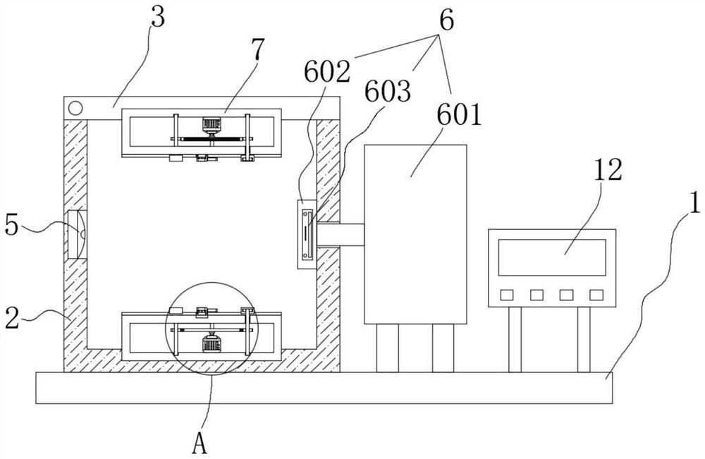
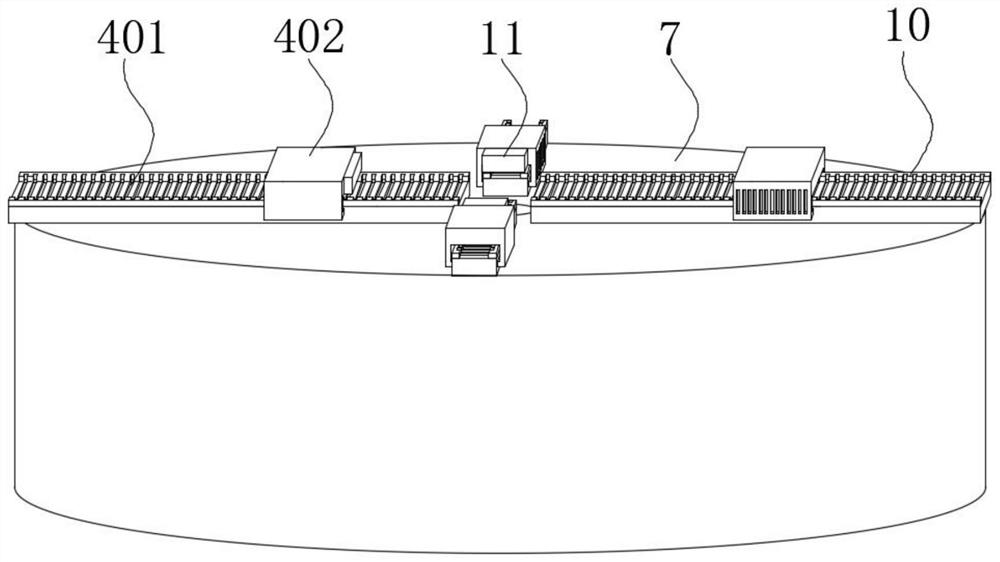
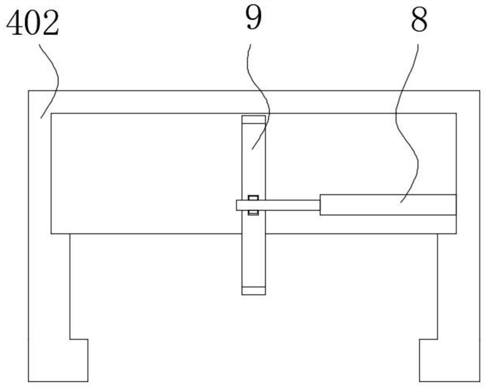
[0031] see Figure 1~4 , in the present invention, a kind of reducer rigidity detection device comprises base plate 1, and the top of base plate 1 is fixedly connected with detection box 2, and the top of detection box 2 is hinged with cover 3, and the bottom of cover 3 and the inside of detection box 2 Both are provided with a clamping assembly 4 , a laser ranging sensor 5 is fixedly installed on the left side inside the detection box 2 , and a detection assembly 6 is fixedly installed on the top of the bottom plate 1 .

[0032] In the present invention, the arrangement of the bottom plate 1 facilitates the support of the whole device. When the user needs to check the rigidity of the main shaft of the reducer, the cover 3 can be opened, and then one end of the ...


PUM


Abstract

The invention discloses a speed reducer rigidity detection device, and belongs to the field of speed reducers. The speed reducer rigidity detection device comprises a bottom plate, wherein the top part of the bottom plate is fixedly connected with a detection box, the top part of the detection box is hinged with a sealing cover, the bottom part of the sealing cover and the interior of the detection box are both provided with clamping assemblies, a laser distance measuring sensor is fixedly installed on the left side of the interior of the detection box, a detection assembly is fixedly arranged on the top part of the bottom plate, each clamping assembly comprises four racks, four moving blocks, eight second gears, four rotating rods, a first gear and a servo motor, mounting boxes are fixedly connected to the interior of the detection box and the bottom part of a sealing cover, and the two servo motors are fixedly mounted in the two mounting boxes correspondingly. According to the speed reducer rigidity detection device, a speed reducer main shaft can be effectively clamped and fixed, the phenomenon that the speed reducer main shaft deviates in the clamping process is reduced, and therefore the detection precision is guaranteed.

Description

technical field [0001] The invention relates to the field of speed reducers, and more specifically, to a speed reducer stiffness detection device. Background technique [0002] The reducer is an independent component composed of gear transmission, worm drive, gear and worm drive enclosed in a rigid shell. It is often used as a reduction transmission device between the prime mover and the working machine. Mechanisms play the role of matching speed and transmitting torque, and are widely used in modern machinery. [0003] The stiffness of the existing reducer spindle needs to be tested after production to ensure the quality and use effect. However, the existing stiffness detection device has a general clamping and fixing effect on the reducer spindle. During the detection process, the reducer The main shaft is prone to offset, which affects the detection accuracy. For this reason, we have introduced a reducer stiffness detection device to solve the above problems. Contents ...

Claims


Application Information

Patent Timeline
Patent Type & Authority Applications(China)
IPC IPC(8): G01M5/00
CPCG01M5/005
Inventor 王振强
Owner 苏州赛岳自动化科技有限公司
Why Eureka
Try Eureka