A method and system for fault location of pseudorandom code based on mmc

A technology of fault distance measurement and pseudo-random code, which is applied in the direction of fault location, fault detection according to conductor type, fault detection by pulse reflection method, etc., to achieve the effect of eliminating power and pulse width, excellent autocorrelation characteristics, and easy generation and replication

Active Publication Date: 2022-08-05
CHINA UNIV OF MINING & TECH
View PDF7 Cites 0 Cited by
  • Summary
  • Abstract
  • Description
  • Claims
  • Application Information

AI Technical Summary

Problems solved by technology

Since the common noise signal is a typical random signal, it is unavoidable in signal processing. At present, there is no method to completely remove the noise, but to minimize the influence of the noise, and the pseudo-random signal has a noise-like Excellent characteristics, it obtains the distance information of the target by calculating the cross-correlation between the transmitted signal and the received signal. The noise signal cannot be cross-correlated with the transmitted signal. Even if the reflected signal contains a noise signal, the noise signal cannot be corrected. At the same time, the pseudo-random signal also has excellent characteristics such as excellent autocorrelation characteristics, large time-bandwidth product, easy generation and replication, etc., so it has been widely used in ground penetrating radar, ultrasonic ranging and other fields

Method used


Image

  • A method and system for fault location of pseudorandom code based on mmc
  • A method and system for fault location of pseudorandom code based on mmc
  • A method and system for fault location of pseudorandom code based on mmc

Examples


Embodiment 1

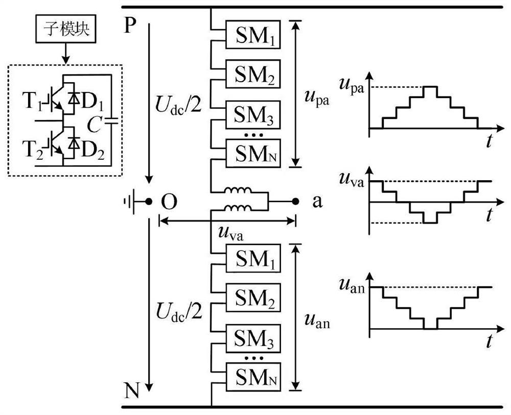
[0049] figure 2 It is a schematic diagram of the topology structure of the modular multilevel converter (MMC), including the positive P and negative N of the DC bus. There are upper and lower bridge arms between the DC buses. The upper bridge arm is connected to the positive P of the bus, and the lower bridge The arm is connected to the negative N of the bus bar, the connection between the upper and lower bridge arms is node a, and node a is connected to the upper and lower bridge arms through inductance respectively; point O is the equivalent neutral point, u vaIt is the output voltage of the AC side of A-phase. The upper and lower bridge arms are provided with several series-connected half-bridge sub-modules (Half Bridge SM, HBSM). The sub-module includes two series-connected IGBTs (T1, T2), and T1 and T2 are respectively provided with anti-parallel diodes D1, D2, T1, T2 are connected in parallel with the capacitor C after being connected in series. The first output termi...

Embodiment 2

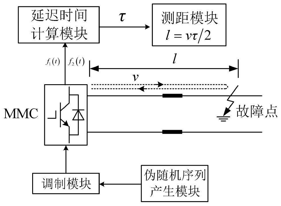
[0083] like figure 1 As shown, an MMC-based pseudo-random code fault location system includes a pseudo-random sequence generation module, a modulation control module, a delay time calculation module, and a ranging module;

[0084] The pseudo-random sequence generation module generates the m-sequence signal; the modulation control module receives the m-sequence signal and controls the MMC DC side voltage to follow the m-sequence signal to switch between two levels; the delay time calculation module receives the MMC DC side voltage signal and reflected wave signal And calculate the delay time between the MMC DC side voltage signal and the reflected wave signal; the ranging module receives the delay time signal and calculates the distance between the fault point and the MMC terminal.


PUM


Abstract

The invention discloses an MMC-based pseudo-random code fault location method and system. The method includes: generating an m-sequence signal composed of 0 and 1; and modulating and controlling the MMC through the m-sequence signal, and the symbols 0 and 1 correspond respectively to The MMC phase unit sub-modules are put into different quantities, thereby controlling the MMC DC side voltage to follow the m-sequence signal to switch between two levels; the MMC DC side voltage propagates along the DC line, and when encountering a fault point, the refraction of the traveling wave occurs, The generated reflected wave returns to the MMC terminal, and the delay time between the DC side voltage signal of the MMC and the reflected wave signal is calculated by the cross-correlation function; the distance between the fault point and the MMC terminal is calculated according to the delay time. The invention successfully eliminates the contradiction between the power and the pulse width of the transmitted signal when the pulse reflection method is used for fault detection and positioning, and improves the fault positioning accuracy.

Description

technical field [0001] The invention relates to the technical field of line fault location, in particular to an MMC-based pseudorandom code fault location method and system. Background technique [0002] Modular multilevel converter (MMC) is a new type of converter topology developed by scholars R.Marquart and A.Lesnicar. It has the advantages of modularization, redundancy, easy expansion, controllability, etc. It realizes large-scale production and integrated design, and has the advantages of low harmonic content and low loss, and has received extensive attention since it was proposed. The emergence of modular multi-level converters not only improves the operation performance and scalability of the power transmission system, but also lays a foundation for the future development of multi-terminal and networked DC transmission technology. [0003] There are many fault location methods for DC transmission lines, and the pulse reflection method is one of the most commonly used...

Claims


Application Information

Patent Timeline
Patent Type & Authority Patents(China)
IPC IPC(8): G01R31/08G01R31/11
CPCG01R31/085G01R31/11
Inventor 王颖杰刘海媛侯贺港毕琪文余储胜王亚娟
Owner CHINA UNIV OF MINING & TECH
Why Eureka
Try Eureka