
Bus resource allocation method and device and related equipment

A resource allocation and bus technology, applied in the field of resource sharing, can solve problems such as long waiting time of the path, failure of the main module to obtain bus resources, system bus performance degradation, etc., to achieve the effect of improving system performance and utilization rate

Pending Publication Date: 2021-10-01
SHANDONG YUNHAI GUOCHUANG CLOUD COMPUTING EQUIP IND INNOVATION CENT CO LTD
View PDF0 Cites 5 Cited by
  • Summary
  • Abstract
  • Description
  • Claims
  • Application Information

AI Technical Summary

Problems solved by technology

Among them, the fixed priority method means that the priority of each main module is determined and will not change with the operation of the system. When multiple main modules request the use of bus resources at the same time, the arbitrator will However, when the high-priority main module is using the bus all the time, the low-priority main module will not get the bus resources, so that the low-priority main module instructions cannot take effect
The time division multiplexing method is mainly to specify a fixed length of time for each master device to occupy the shared resource in advance, and when the time ends, the shared resource will be allocated to another master device; however, this method has high requirements for the division of time slices. If If the division is unreasonable, the waiting time of the channel with high priority and high bandwidth requirements will be prolonged, and the bus performance of the system will be degraded. In addition, in the actual application process, the bandwidth of data read and write requests between different master and slave devices changes dynamically. If a fixed time slice is used, it will definitely cause low efficiency of arbitration allocation in a certain period of time, which will affect the performance of the bus and SOC chip

Method used


Image

  • Bus resource allocation method and device and related equipment
  • Bus resource allocation method and device and related equipment
  • Bus resource allocation method and device and related equipment

Examples


Embodiment Construction

[0054]The core of this application is to provide a bus resource allocation method, which can realize the reasonable allocation of bus resources, effectively improve the utilization of bus resources, and further improve system performance; another core of this application is to provide A bus resource allocation device, system, and computer-readable storage medium also have the above beneficial effects.

[0055] In order to describe the technical solutions in the embodiments of the present application more clearly and completely, the technical solutions in the embodiments of the present application will be introduced below in conjunction with the drawings in the embodiments of the present application. Apparently, the described embodiments are only some of the embodiments of this application, not all of them. Based on the embodiments in this application, all other embodiments obtained by persons of ordinary skill in the art without making creative efforts belong to the scope of p...


PUM


Abstract

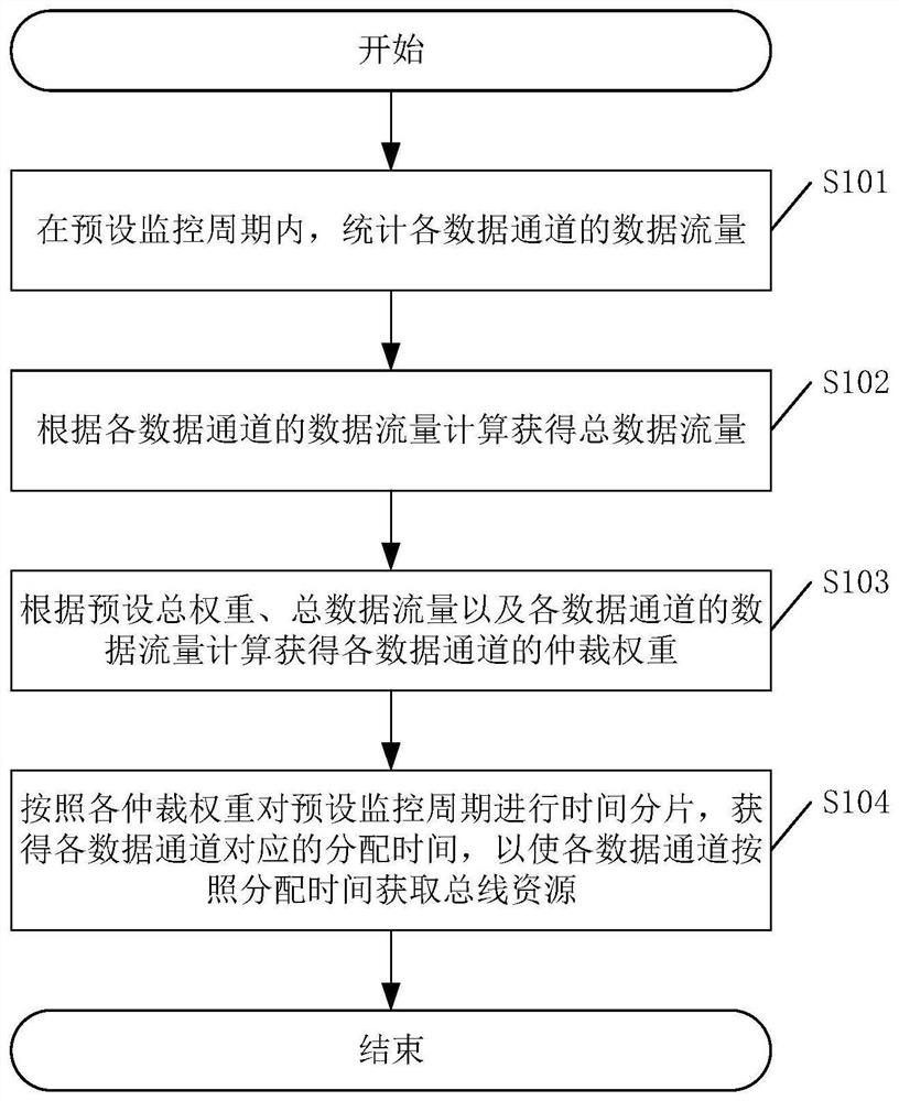
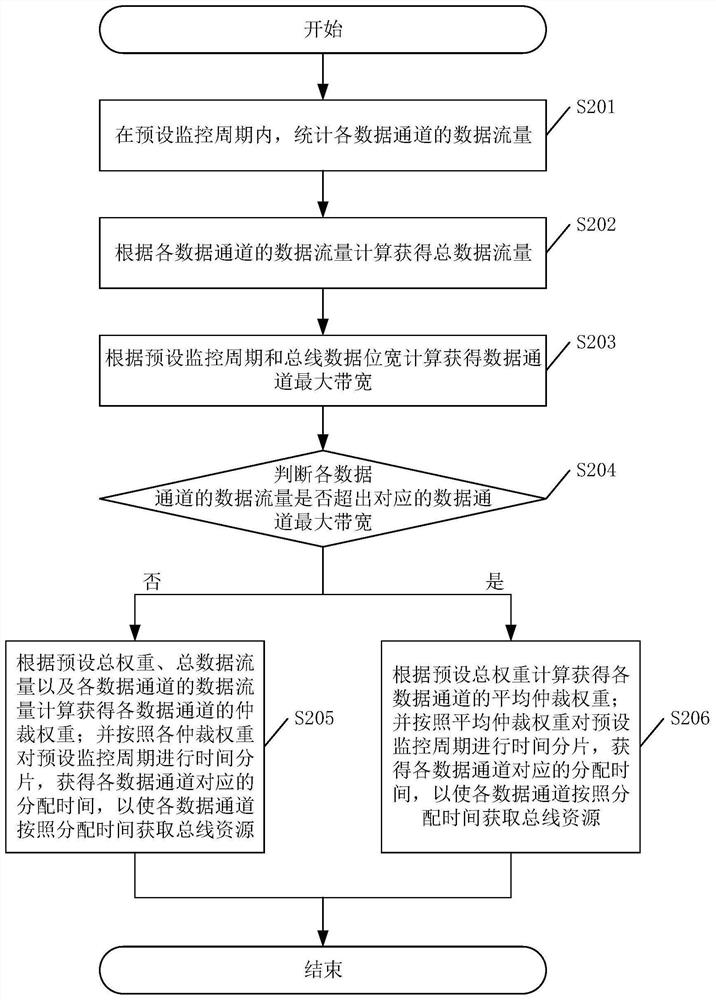
The invention discloses a bus resource allocation method, which comprises the following steps: counting data traffic of each data channel in a preset monitoring period; calculating to obtain total data traffic according to the data traffic of each data channel; calculating to obtain an arbitration weight of each data channel according to a preset total weight, the total data traffic and the data traffic of each data channel; performing time fragmentation on the preset monitoring period according to each arbitration weight, and obtaining allocation time corresponding to each data channel, so that each data channel obtains bus resources according to the allocation time. According to the bus resource allocation method, reasonable allocation of the bus resources can be realized, the utilization rate of the bus resources is effectively improved, and the system performance is further improved. The invention further discloses a bus resource allocation device and system and a computer readable storage medium which all have the above beneficial effects.

Description

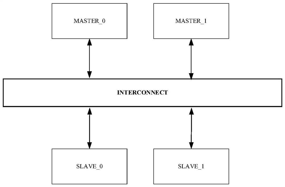
technical field [0001] The present application relates to the technical field of resource sharing, in particular to a bus resource allocation method, and also to a bus resource allocation device, system, and computer-readable storage medium. Background technique [0002] With the continuous development of integrated circuits, the requirements for processing speed and performance of SOC (System on Chip, System on Chip) chips are getting higher and higher. As the central bridge connecting each module, the system bus has an important impact on the performance of the SOC system, especially in a system with multiple master devices and multiple slave devices, the arbitration mechanism of the bus will affect the read and write efficiency of multiple data, Then affect the performance of the SOC chip. [0003] In the related art, the multi-user arbitration method of the system bus mainly includes a fixed priority method and a time division multiplexing method. Among them, the fixed...

Claims


Application Information

Patent Timeline
Patent Type & Authority Applications(China)
IPC IPC(8): G06F9/50
CPCG06F9/5027Y02D10/00
Inventor 孙旭
Owner SHANDONG YUNHAI GUOCHUANG CLOUD COMPUTING EQUIP IND INNOVATION CENT CO LTD
Learn More