Supercharge Your Innovation With Domain-Expert AI Agents!

Automatic tinning equipment for special-shaped wire harness

A special-shaped wire and tin-dipping technology, which is used in equipment for dismantling/armoring cables, equipment for connecting/terminating cables, welding equipment, etc. The effect of low scrap rate, uniform tin dip and high efficiency

Active Publication Date: 2021-10-01
SHUNDE POLYTECHNIC +1
View PDF4 Cites 0 Cited by
  • Summary
  • Abstract
  • Description
  • Claims
  • Application Information

AI Technical Summary

Problems solved by technology

[0002] At present, there are many automatic tinning equipment for wire harnesses on the market, most of which are used for straight ordinary wire harnesses, and for special-shaped wire harnesses with a bent structure that looks like a concave , there is no mature equipment yet, you can only rely on manual work to break the bent part of the special-shaped wire harness along the vertical direction to avoid the wire harness, then cut and peel it, and then dip it in tin
This manual operation method is inefficient, with uneven soldering and high scrap rate

Method used


Image

  • Automatic tinning equipment for special-shaped wire harness
  • Automatic tinning equipment for special-shaped wire harness
  • Automatic tinning equipment for special-shaped wire harness

Examples


Embodiment Construction

[0017] The specific embodiments of the present invention will be further described below in conjunction with the accompanying drawings. It should be noted here that the descriptions of these embodiments are used to help understand the present invention, but are not intended to limit the present invention. In addition, the technical features involved in the various embodiments of the present invention described below may be combined with each other as long as they do not constitute a conflict with each other.

[0018] In the description of the present invention, the orientation or positional relationship indicated by the terms "longitudinal", "transverse", "upper" and "lower" are based on the orientation or positional relationship shown in the drawings, and are only for the convenience of describing the present invention rather than Requirements that the invention must be constructed and operated in a particular orientation are not to be construed as limitations on the inventio...


PUM


Abstract

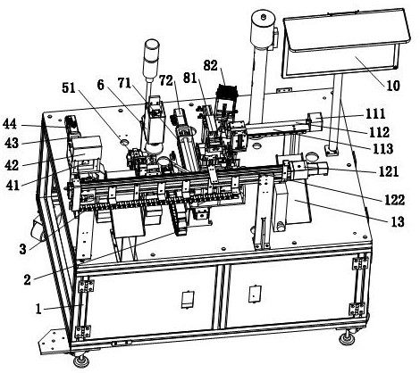
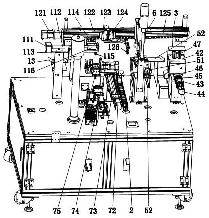
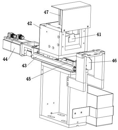
The invention relates to automatic tinning equipment for a special-shaped wire harness. The automatic tinning equipment is characterized by comprising a rack, a conveying mechanism, a cutting mechanism, a peeling mechanism, a detection mechanism, a tinning conveying mechanism, a tinning box mechanism and a material falling groove, wherein the conveying mechanism, the cutting mechanism, the peeling mechanism, the detection mechanism, the tinning conveying mechanism and the material falling groove are all arranged on the rack, the cutting mechanism, the peeling mechanism, the detection mechanism, the tinning conveying mechanism and the material falling groove are sequentially arranged from left to right, the tinning box mechanism is located on the rack and located beside the tinning conveying mechanism so as to conveniently achieve tinning, and the conveying mechanism sucks special-shaped wire harnesses, sequentially places the special-shaped wire harnesses on the cutting mechanism, the peeling mechanism, the detection mechanism, the tinning conveying mechanism and the material falling groove to complete the working procedures of cutting, peeling and tinning, and outputs the special-shaped wire harnesses. The equipment has the advantages that the bent part of the special-shaped wire harness can be automatically rotated by a certain angle to expose the to-be-cut wire harness, so that the special-shaped wire harness is automatically cut, peeled and tinned, the efficiency is high, tinning is uniform, and the rejection rate is low.

Description

technical field [0001] The invention relates to an automatic tin-staining device for special-shaped wire harnesses. Background technique [0002] At present, there are many automatic tinning equipment for wire harnesses on the market, most of which are used for ordinary wire harnesses that are straight, but for special-shaped wire harnesses with a bent structure that looks like a concave shape, there is no mature equipment, and the special-shaped wire harness can only be bent manually. The folded part is broken along the vertical direction to avoid the empty wire harness, then cut and peeled, and then dipped in tin. This manual operation has low efficiency, uneven tin dipping, and high scrap rate. Contents of the invention [0003] The purpose of the present invention is to overcome the deficiencies of the prior art and provide an automatic dipping equipment for special-shaped wire harnesses, which can automatically turn the bent part of the special-shaped wire harness to...

Claims


Application Information

Patent Timeline
Patent Type & Authority Applications(China)
IPC IPC(8): H01R43/02H01R43/28H02G1/12H02G1/14B23K3/06B23K3/08
CPCH01R43/0235H01R43/28H02G1/14H02G1/1248B23K3/06B23K3/0646B23K3/08Y02W30/82
Inventor 吴晖辉许柳信陈珏彰
Owner SHUNDE POLYTECHNIC
Features
  • R&D
  • Intellectual Property
  • Life Sciences
  • Materials
  • Tech Scout
  • Unparalleled Data Quality
  • Higher Quality Content
  • 60% Fewer Hallucinations
Learn More