Pose control method and optical navigation system and surgical robot system applicable to pose control method

A control method and optical navigation technology, applied in surgical navigation systems, surgical manipulators, surgical robots, etc., can solve problems affecting surgical efficiency and fluency, achieve high integration, wide application scenarios, and reduce infection effects.

Active Publication Date: 2021-10-08
SUZHOU MICROPORT ORTHOBOT CO LTD
View PDF7 Cites 5 Cited by
  • Summary
  • Abstract
  • Description
  • Claims
  • Application Information

AI Technical Summary

Problems solved by technology

[0004] The object of the present invention is to provide a pose control method and its applicable optical navigation system, surgical robot system, computer equipment, support device and computer-readable storage medium , which can solve the problem that the markers in the optical surgical navigation system in the prior art are blocked and affect the efficiency and fluency of the operation

Method used


Image

  • Pose control method and optical navigation system and surgical robot system applicable to pose control method
  • Pose control method and optical navigation system and surgical robot system applicable to pose control method
  • Pose control method and optical navigation system and surgical robot system applicable to pose control method

Examples


Embodiment 1

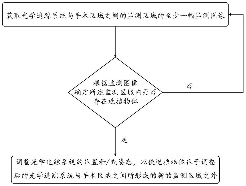
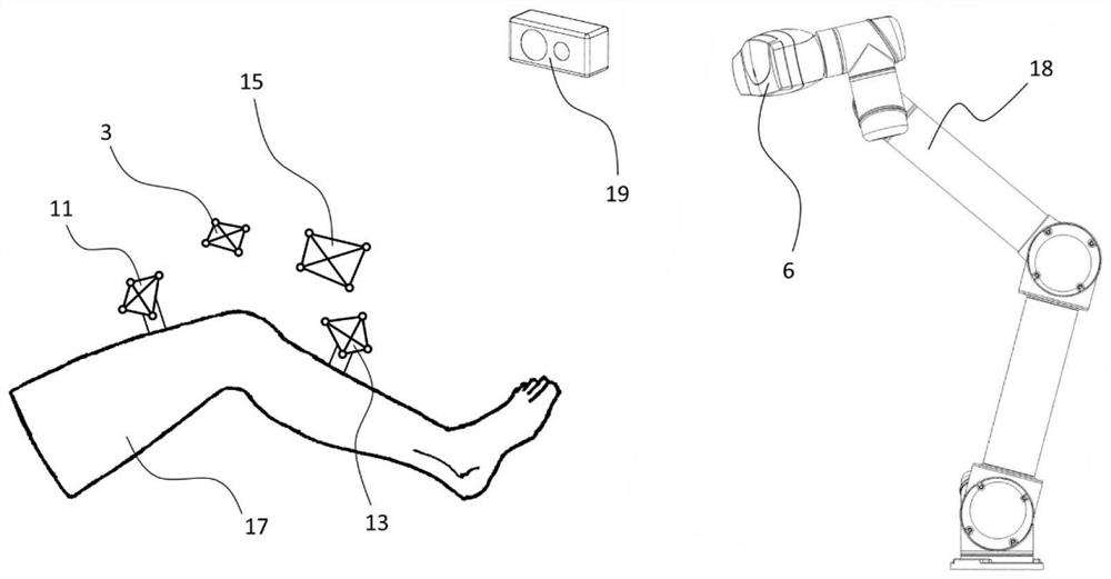
[0077] In the pose control method of the optical tracking system in Embodiment 1, the positioning device is used to obtain at least one monitoring image of the monitoring area. In this embodiment, the positioning device is used as a depth camera for detailed introduction, as shown in image 3 As shown, the positioning device uses the depth camera 19 to detect the monitoring area, and the specific pose control method can be as follows:

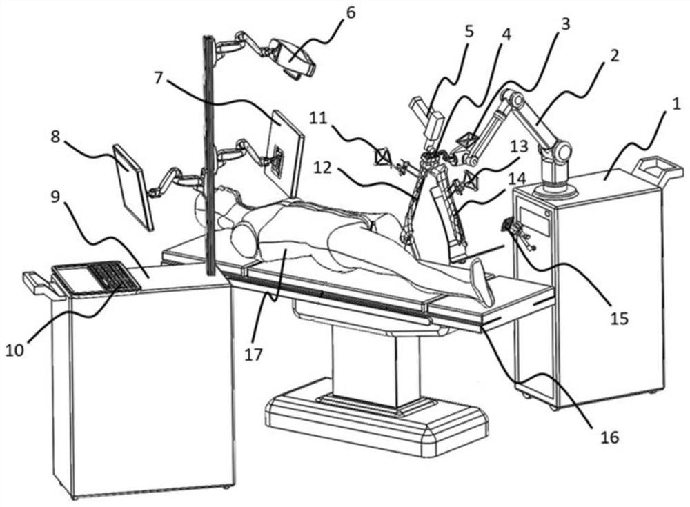
[0078] S1: first set and fix the optical markers, wherein the optical markers can include the femoral markers 11, tibial markers 13, tool markers 3 and base markers 15 set on the corresponding positions as described above, and the optical markers The tracking system 6 is installed on a supporting device, wherein the supporting device can be a mechanical arm 18, or other mobile platforms capable of moving. This embodiment takes the supporting device as the mechanical arm 18 as an example for introduction;

[0079] S2: The optical tracking system...

Embodiment 2

[0100] In Example 2, the positioning device uses a binocular camera to monitor obstacles, and the specific pose control method is as follows:

[0101] Y1: Similar to S1 in Example 1, first set and fix the optical markers, wherein the optical markers can include femoral markers 11, tibial markers 13, tool markers 3 and base markers 15 set on corresponding positions etc., the optical tracking system 6 is installed on the mechanical arm 18;

[0102] Y2: Similar to step S2 of Embodiment 1, the optical tracking system 6 tracks the position information of the optical marker in real time, and determines the monitoring area according to the position of the optical tracking system 6 and the optical marker;

[0103] Similarly, the optical tracking system 6 tracks the position information of the optical markers in real time, specifically including: according to the position information of a plurality of the optical markers, a minimum enclosing sphere 20 can be obtained, and a plurality o...


PUM


Abstract

The invention provides a pose control method and an optical navigation system and a surgical robot system applicable to the pose control method. The pose control method comprises the following steps of acquiring at least one monitoring image of a monitoring area between an optical tracking system and a surgical area; determining the surgical area based on the position of at least one optical marker; and when it is determined that a shielding object exists in the monitoring area according to the monitoring image, adjusting the position and/or posture of the optical tracking system so as to enable the shielding object to be located outside a new monitoring area formed between the adjusted optical tracking system and the operation area. The pose control method can solve the problem that in the prior art, a marker in an optical surgical navigation system is shielded, so that the surgical efficiency and smoothness are affected.

Description

technical field [0001] The invention relates to the technical field of medical equipment, in particular to a posture control method and an applicable optical navigation system and surgical robot system. Background technique [0002] The emergence of the surgical navigation system is in line with the development trend of precision surgery. The surgical navigation system accurately corresponds the patient's preoperative or intraoperative image data to the patient's anatomical structure on the operating bed, and tracks the surgical instruments during the operation. The form of the probe is updated and displayed in real time, so that the doctor can see at a glance the position of the surgical instrument relative to the patient's anatomical structure, making the surgical operation faster, more accurate and safer. The surgical navigation system provides richer reference information and more accurate guidance for surgical operations through the analysis of patients' medical images ...

Claims


Application Information

Patent Timeline
Patent Type & Authority Applications(China)
IPC IPC(8): A61B34/20A61B34/32A61B34/00
CPCA61B34/20A61B34/32A61B34/70A61B2034/2055A61B2034/2057A61B2034/2065A61B2034/2068
Inventor 刘赫何锐邵辉
Owner SUZHOU MICROPORT ORTHOBOT CO LTD
Why Eureka
Try Eureka