Multifunctional printing processing system

A processing system and multi-functional technology, applied in printing, printing presses, rotary printing presses, etc., can solve the problems of affecting quality, unstable effect, low operation efficiency of thick paper, etc., to reduce costs and error rates, and improve work. The effect of efficiency

Pending Publication Date: 2021-10-08
MARKETING MFG & TECH SHANGHAI
View PDF0 Cites 0 Cited by
  • Summary
  • Abstract
  • Description
  • Claims
  • Application Information

AI Technical Summary

Problems solved by technology

For post-press processing of different surface finishes, such as glazing, lamination, casting, calendering, bronzing, etc., the powder spraying on the surface of the substrate will be obvious, which will greatly affect the quality of subsequent processing, so that it cannot meet the requirements of printed products. Where high gloss or surface consistency are required
[0003] The powder removal method in the prior art is to transfer the base material through the conveyor belt, the effect is not stable, it is not suitable for high-speed operation, and it is only suitable for thick paper and the operation efficiency is low, so it can only meet the needs of printed products. Products with low surface requirements

Method used


Image

  • Multifunctional printing processing system
  • Multifunctional printing processing system
  • Multifunctional printing processing system

Examples


Embodiment 1

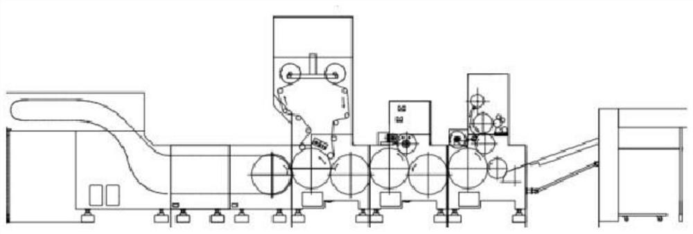
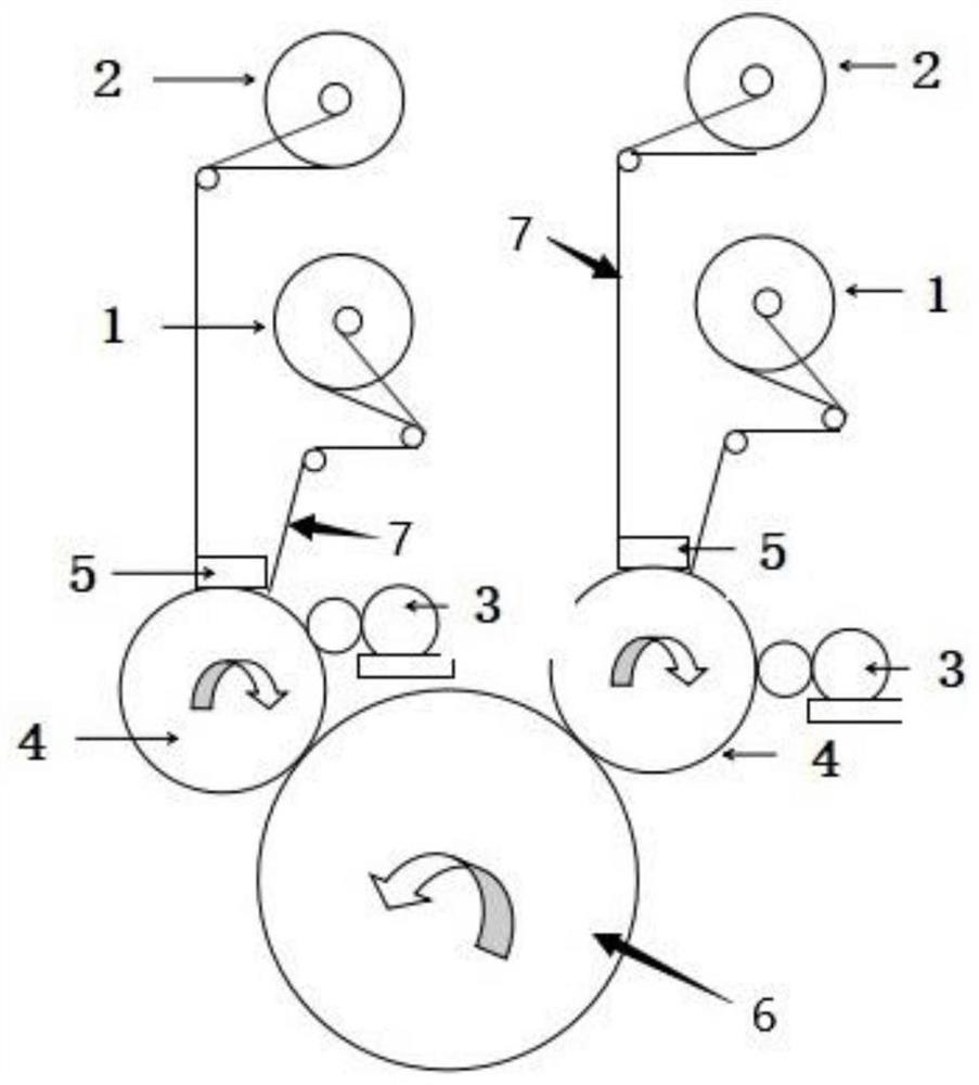
[0035] The printed paper enters the depowdering unit through the jaws of the feeder, and the roller coating device 3 in the depowdering unit transfers water to the rubber roller 4, and the rubber roller 4 with water is pressed together to remove the surface of the printed sheet. Paper dust is stained on the rubber surface of the rubber roller 4 surface; at the same time, the pressed porous device 5 sprays water to the non-woven fabric 7 released from the unwinding shaft 1, and the non-woven fabric 7 is bonded to the rubber roller 4, thereby erasing the rubber roller 4 surface. Paper powder, after the set number of printed sheets is reached, the porous device 5 is released, and the winding shaft 2 rewinds the polluted non-woven fabric; after that, the paper passes through the roller coating device 3 of the second set of powder removal unit to transfer the water to the rubber roller 4 On the surface, the paper powder on the surface of the printed sheet is stained on the surface o...

Embodiment 2

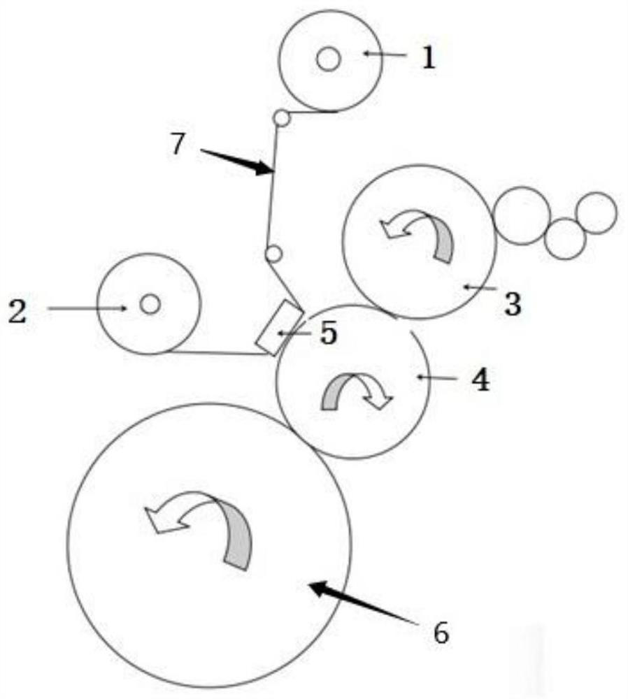
[0037] The printed paper enters the powder removal unit through the jaws of the feeder. The roller coating device 3 of the powder removal unit transfers water to the rubber roller 4, and the rubber roller 4 with water is pressed together to remove the paper on the surface of the printed sheet. Powder, onto the surface of the eraser. At the same time, the pressed porous device 5 sprays water on the non-woven fabric 7 discharged from the unwinding shaft 1, and the non-woven fabric 7 is attached to the rubber roller 4, thereby erasing the paper powder on the surface of the rubber roller 4. After the set number of printed sheets is reached, the porous device 5 from the pressure, the winding shaft 2 will take up the polluted non-woven fabric. After powder removal, the paper enters the coating unit and is partially coated by the flexo printing structure. The coated paper then enters the casting curing unit and is bonded with the holographic casting film. After UV curing, the paper a...

Embodiment 3

[0039] The second set of powder removal unit can be used as a coating unit to save costs and improve efficiency, as follows:

[0040] The printed paper enters the first set of depowdering unit through the teeth gripper after the feeder enters, and the roller coating device 3 of the depowdering unit transfers water to the surface of the rubber roller 4, and the rubber roller 4 with water is pressed together The paper dust on the surface of the printed sheet sticks to the surface of the rubber. At the same time, the pressed porous device 5 sprays water on the non-woven fabric 7 released from the unwinding shaft 1, and the non-woven fabric 7 is attached to the rubber roller 4, thereby erasing the paper powder on the surface of the rubber roller 4. After the set number of printed sheets is reached, the porous device 5 from the pressure, the winding shaft 2 will take up the polluted non-woven fabric. After passing through the first set of powder removal unit, the paper enters the ...


PUM


Abstract

The invention relates to the field of printing processing systems, and particularly relates to a multifunctional printing processing system. The multifunctional printing processing system comprises a feeder device, a powder removing unit, a coating unit, a casting curing unit and a paper collecting unit; the powder removing unit comprises an unwinding shaft, a winding shaft, a roll coating device, a rubber roller, a porous device, a main winding shaft and non-woven fabric; the main winding shaft is attached to one side of the rubber roller, and the other side of the rubber roller is attached to one side of the roll coating device; the inner side of the porous device is attached to the surface of one side of the rubber roller; the unwinding shaft is arranged on one side of the porous device, and the winding shaft is arranged on the other side of the porous device; the non-woven fabric is unwound from the unwinding shaft, passes through the inner side of the porous device and is attached to the surface of the rubber roller; and the non-woven fabric is recycled through the winding shaft. Compared with the prior art, dust impurities on printing paper can be effectively removed, the non-woven fabric on the unwinding shaft and the winding shaft is wound, water is sprayed through the porous device, then the surface of the rubber roller is scrubbed, and the problem that the rubber roller needs to be shut down and cleaned after being used many times is effectively solved.

Description

technical field [0001] The invention relates to the field of printing processing systems, in particular to a multifunctional printing processing system. Background technique [0002] As we all know, in order to achieve cost reduction, back printing and high-speed printing, printing factories need to spray powder after printing with ordinary ink to reduce or avoid paper sticking and back printing after printing. For post-press processing of different surface finishes, such as glazing, lamination, casting, calendering, bronzing, etc., the powder spraying on the surface of the substrate will be obvious, which will greatly affect the quality of subsequent processing, so that it cannot meet the requirements of printed products. In requirements such as high gloss or surface consistency. [0003] The powder removal method in the prior art is to transfer the base material through the conveyor belt, the effect is not stable, it is not suitable for high-speed operation, and it is onl...

Claims


Application Information

Patent Timeline
Patent Type & Authority Applications(China)
IPC IPC(8): B41F17/00B41F13/02B41F23/00B41F35/02
CPCB41F17/00B41F13/02B41F23/002B41F35/02
Inventor 吴德明任烨
Owner MARKETING MFG & TECH SHANGHAI
Why Eureka
Try Eureka