
Lifting hydraulic system

A hydraulic system and connected technology, applied in the field of hydraulic system, can solve the problems of crane or the whole platform falling down, hidden dangers and so on.

Active Publication Date: 2021-10-08
WUHAN MARINE MACHINERY PLANT
View PDF5 Cites 0 Cited by
  • Summary
  • Abstract
  • Description
  • Claims
  • Application Information

AI Technical Summary

Problems solved by technology

The lifting hydraulic system in the prior art can usually only realize the lifting and lowering of cargo. However, when the fixed platform crane is hoisting with the supply ship, if the hook of the fixed platform crane is accidentally hooked on the supply ship, When the supply ship starts to move without knowing it or the state is uncontrollable, if the pull rope cannot be quickly separated from the lifting equipment, the crane or the entire platform will be dragged down by the supply ship, causing serious safety hazards

Method used


Image

  • Lifting hydraulic system

Examples


Embodiment 1

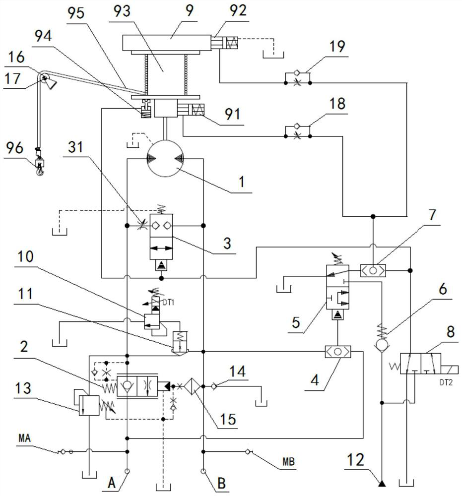
[0058] A lifting hydraulic system, the lifting hydraulic system includes a motor 1, a balance valve 2, a first reversing valve 3, a first shuttle valve 4, a second reversing valve 5, a first one-way valve 6, a second Shuttle valve 7, electromagnetic reversing valve 8, winch assembly 9, first working oil port A of the system and second working oil port B of the system; the first working oil port A of the system passes through the balance valve 2 and a working oil of the motor 1 The other working oil port of the motor 1 is connected with the second working oil port B of the system, and the second working oil port B of the system is connected with the control oil port of the balance valve 2 and the first shuttle valve 4 at the same time. One oil inlet is connected, the other oil inlet of the first shuttle valve 4 is connected with the first working oil port A of the system, and the oil outlet of the first shuttle valve 4 is connected with the control oil of the second reversing va...

Embodiment 2

[0060] Embodiment 2 is basically the same as Embodiment 1, and its difference is:

[0061]The lifting hydraulic system also includes a pilot-operated proportional relief valve 10 and a two-way cartridge valve 11, the oil outlet of the pilot-operated proportional relief valve 10 is connected to the oil tank, and the inlet port of the pilot-operated proportional relief valve 10 The oil port is connected with the control oil port of the two-way cartridge valve 11, the oil inlet port of the two-way cartridge valve 11 is connected with the oil circuit between the motor 1 and the balance valve 2, and the two-way cartridge valve 11 The oil outlet is connected with the second working oil port B of the system; the lifting hydraulic system also includes a one-way relief valve 13, and the oil inlet of the one-way relief valve 13 is connected to the inlet of the two-way cartridge valve 11. The oil ports communicate with each other, and the oil outlet of the one-way overflow valve 13 commu...

Embodiment 3

[0063] Embodiment 3 is basically the same as Embodiment 2, and its difference is:

[0064] One end of the stay rope 95 is fixed on the drum 93, and the other end of the stay rope 95 is connected with the hook 96 after passing through the guide pulley 16, and the middle part of the guide pulley 16 is provided with a pin sensor 17; the second shuttle valve The oil outlet between the oil outlet of 7 and the control end of the disc brake 91 is provided with a first one-way throttle valve 18; the oil between the oil outlet of the second shuttle valve 7 and the control end of the band brake 92 A second one-way throttle valve 19 is arranged on the road; a throttle valve 31 is arranged at a working oil port of the first reversing valve 3 .


PUM


Abstract

The invention relates to a lifting hydraulic system. The lifting hydraulic system comprises a motor, a balance valve, a first reversing valve, a first shuttle valve, a second reversing valve, a first one-way valve, a second shuttle valve, an electromagnetic reversing valve, a winch assembly, a system first working oil port and a system second working oil port, wherein the system first working oil port communicates with the system second working oil port sequentially through the balance valve and the motor; the first shuttle valve is connected with the winch assembly sequentially through the second reversing valve and the second shuttle valve; and the first reversing valve communicates with a 3MPa constant-pressure oil source through the electromagnetic reversing valve. A coil of the electromagnetic reversing valve is electrified to enable a control oil port of the first reversing valve to communicate with the 3MPa constant-pressure oil source in case of emergency, and therefore, the motor rotates freely under the traction of the load,. Meanwhile a rope pressing device is opened to achieve automatic rope abandoning.

Description

technical field [0001] The invention relates to a hydraulic system, in particular to a lifting hydraulic system, which is particularly suitable for lifting and hoisting operations of fixed platforms and supply ships. Background technique [0002] Lifting hydraulic systems are widely used in various lifting equipment. The lifting hydraulic system in the prior art can usually only realize the lifting and lowering of cargo. However, when the fixed platform crane is hoisting with the supply ship, if the hook of the fixed platform crane is accidentally hooked on the supply ship, And when the supply ship starts to move without knowing it or the state is uncontrollable, if the stay rope cannot be separated from the lifting equipment quickly, the crane or the entire platform will be dragged down by the supply ship, causing serious safety hazards. [0003] Therefore, there is a need for a hoisting hydraulic system that can control the tension of the stay rope and can actively abando...

Claims


Application Information

Patent Timeline
Patent Type & Authority Applications(China)
IPC IPC(8): B66C23/52B66D1/08B66D1/24B66D1/52B66D5/02B66D5/10B66D5/12F15B13/02
CPCB66C23/52B66D1/08B66D1/24B66D1/52B66D5/02B66D5/10B66D5/12F15B13/02F15B13/027F15B2013/004
Inventor 王进峰陆兆鹏叶凯刘鑫胜
Owner WUHAN MARINE MACHINERY PLANT
Learn More