Supercharge Your Innovation With Domain-Expert AI Agents!

Tension locking device

A technology of lockers, pulls, applied in the direction of sheet pile walls, protection devices, building construction, etc.

Inactive Publication Date: 2021-10-08
深圳市普赛特建筑工程技术有限公司
View PDF0 Cites 0 Cited by
  • Summary
  • Abstract
  • Description
  • Claims
  • Application Information

AI Technical Summary

Problems solved by technology

[0003] In view of this, the purpose of the embodiment of the present invention is to provide a tension locker to solve the problem of tension locking of prestressed anti-floating anchor rods in the prior art

Method used


Image

  • Tension locking device
  • Tension locking device

Examples


Embodiment 1

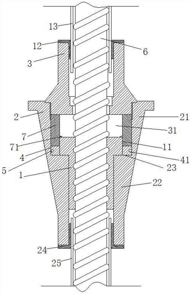
[0024] Such as figure 1 The tension locker shown includes a sleeve 1, a bearing sleeve 2, a gland 3, a slider 4, and a rubber ring 5;

[0025] The sleeve 1 is threaded on the peripheral surface of the finish-rolled rebar 6; one end of the sleeve 1 extends radially away from the finish-rolled rebar 6 with a ring eaves 11 integrally;

[0026] The gland 3 is positioned above the sleeve 1 and is installed on the peripheral surface of the finish-rolled threaded steel bar 6 through the first sealing cover 12 and the first sleeve 13; the first sealing cover 12 and the The upper end of the gland 3 is threaded, and the first sleeve 13 is sleeved on the outer surface of the finish-rolled threaded steel bar 6 .

[0027] A movable space 31 for the movement of the sleeve 1 is provided between the gland 3 and the sleeve 1;

[0028] Such as figure 1 As shown, in the initial state, the slider 4 is fixed outside the ring eaves 11 of the sleeve 1;

[0029] Preferably, the carrying sleeve 2 ...


PUM


Abstract

The invention discloses a tension locking device. The tension locking device comprises a sleeve, a bearing sleeve, a pressing cover, a sliding block and a rubber ring. The sleeve is in threaded connection with the peripheral surface of a finish-rolled twisted steel; one end of the sleeve radially extends away from the finish-rolled twisted steel to form a ring eave; the pressing cover is positioned above the sleeve and is mounted on the peripheral surface of the finish-rolled twisted steel; and a certain space is reserved between the pressing cover and the sleeve for the sleeve to move upwards when the sleeve is stressed. According to the tension locking device, the sleeve is mounted on the peripheral surface of the finish-rolled twisted steel under the action of external force and moves in the stress direction of the finish-rolled twisted steel, and when the displacement height is larger than the height of the sliding block, the sliding block moves to the position below the annular eave of the sleeve under the combined action of resistance of the upper pressing cover and resilience force of the rubber sleeve, after the external force is removed, the sliding block is clamped below the ring eave of the sleeve, so that the sleeve is prevented from recovering to the original position, the finish-rolled twisted steel is prevented from recovering to the original shape, and a deformation increment section of the finish-rolled twisted steel has tensile stress.

Description

technical field [0001] Embodiments of the present invention relate to the field of geotechnical engineering, and in particular to a tension locker. Background technique [0002] The use of prestressed anti-floating anchors is the development trend of anti-floating anchors. In the application, holes need to be reserved at the connection between the anchor and the concrete floor for tension locking of the prestressed anti-floating anchors. Even though the holes are closed in the later stage However, there are still hidden dangers of water seepage, which greatly affects the use and popularization of prestressed anti-floating anchor rods in engineering. Contents of the invention [0003] In view of this, the purpose of the embodiments of the present invention is to provide a tension locker to solve the problem of tension locking of prestressed anti-floating anchor rods in the prior art. [0004] A tension locker, including a sleeve, a bearing sleeve, a gland, a slider, and a ...

Claims


Application Information

Patent Timeline
Patent Type & Authority Applications(China)
IPC IPC(8): E02D5/74E02D31/12E04G21/12
CPCE02D5/74E02D31/12E04G21/12
Inventor 李冬晗李宏王鑫垚
Owner 深圳市普赛特建筑工程技术有限公司
Features
  • R&D
  • Intellectual Property
  • Life Sciences
  • Materials
  • Tech Scout
  • Unparalleled Data Quality
  • Higher Quality Content
  • 60% Fewer Hallucinations
Learn More