
Patsnap Eureka
For R&D, Patsnap Eureka makes reading and utilizing patents & technical documents easy.
Patsnap Eureka AIR
Designed for self-driven R&D workflows. Generate viable solutions, solve complex R&D challenges, empower your innovation with AI.

Patsnap Eureka Materials
Designed for material experts only. Revolutionize your material R&D, from search, analyze, to developing new materials.

TechResearch
Generate reliable direction feasibility study reports for your R&D in just a few steps.

TechSeek
Discover and master advanced knowledge NOW. Basics, ideas, possibilities, all at once.

TechMind
As an expert in R&D Theories, TechMind can generates customized viable solutions instantly.

TechRisk
Analyze your overall solution with one click, know your potential R&D risks in advance.

TechMonitor
Get weekly tech updates, stay abreast of the latest tech innovations and key insights.
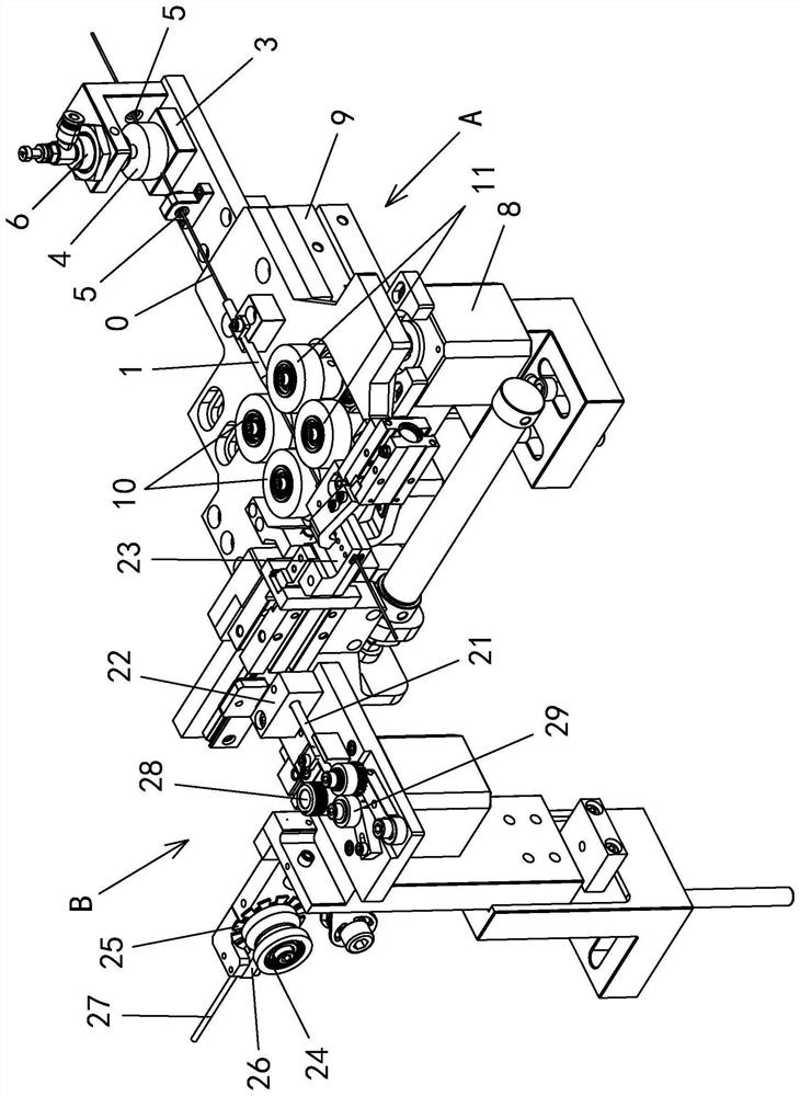
Sleeve threading device
A technology of threading device and bushing, applied in coil manufacturing, electrical components, inductor/transformer/magnet manufacturing, etc., can solve the problems of high labor intensity, low manual operation efficiency, and high labor cost, and achieve labor cost saving, optimal Industrial efficiency and practicality, the effect of avoiding insufficient friction
- Summary
- Abstract
- Description
- Claims
- Application Information
AI Technical Summary
Problems solved by technology
Method used
Image

Examples
Embodiment
[0050]Embodiment: The following will clearly illustrate this case with drawings and detailed descriptions. After any person skilled in the art understands the embodiment of this case, he can change and modify it by the technology taught in this case without departing from the spirit of this case. with range.
[0051] The terminology used herein is for the purpose of describing particular embodiments only, and is not intended to be limiting of the present case. Singular forms such as "a", "the", "the", "this" and "the", as used herein, also include plural forms.
[0052] The terms “first” and “second” used herein do not refer to a sequence or order, nor are they used to limit the present application, but are only used to distinguish components or operations described with the same technical terms.
[0053] As used herein, "connection" or "positioning" can mean that two or more components or devices are in direct physical contact with each other, or that they are in indirect ph...
PUM
 Abstract
Description
Claims
Application Information
 - R&D Engineer
- R&D Manager
- IP Professional
- Industry Leading Data Capabilities
- Powerful AI technology
- Patent DNA Extraction
Browse by: Latest US Patents, China's latest patents, Technical Efficacy Thesaurus, Application Domain, Technology Topic, Popular Technical Reports.
© 2024 PatSnap. All rights reserved.Legal|Privacy policy|Modern Slavery Act Transparency Statement|Sitemap|About US| Contact US: help@patsnap.com