Asphalt pavement crack filling device

A technology of asphalt pavement and asphalt, which is applied in the field of asphalt pavement crack filling device, which can solve the problems of pavement damage, increased workload, and reduced filling effect

Inactive Publication Date: 2021-06-25
霍延敏
View PDF0 Cites 7 Cited by
  • Summary
  • Abstract
  • Description
  • Claims
  • Application Information

AI Technical Summary

Problems solved by technology

[0002] With the rapid development of my country's social economy, the comprehensive service quality requirements for road traffic are getting higher and higher. However, after a period of use on the road, there will be cracks, potholes, ruts and other diseases on the surface. Among them, cracks are various types of road surface. One of the most common and most likely to occur diseases, the hazards of road cracks not only affect the appearance of the road and driving comfort, but if the cracks are not sealed and repaired in time, it is easier to further expand, making rainwater and other sundries along the road Cracks enter the surface structure and subgrade, causing structural damage to the road, resulting in a decrease in the load-carrying capacity of the road surface, accelerating local or piece-by-piece damage to the road surface, and shortening the service life of the road. Therefore, timely repairs are required after cracks are found;
[0003] For small and medium-sized cracks, the commonly used repair method is the crack filling method, which mainly includes slotting-cleaning-filling, that is, slotting treatment along the direction of the crack, the size of the slot has a certain standard, and then the impurities in the slot are removed. After the material is cleaned up, the joint filling is started. The common method of joint filling is to use the joint filling machine, and the nozzle on the joint filling machine will walk along the opened groove, so as to input the joint filling glue into the crack. However, the traditional joint filling machine When in use, the nozzle cannot always be compared with the notch under manual operation, that is, the nozzle may deviate when moving, so that the joint glue or asphalt leaks out of the groove, which not only wastes raw materials, but also requires subsequent processing , increase the workload, in addition, there is a gap with different widths from the beginning to the end, and the size of the groove will also change. If the nozzle is still moving at the original speed, it will cause the slot width to be filled with glue. Filling and overflowing of the slot where the slot is narrow, not only the repair is incomplete, but the filling effect is reduced, but also follow-up processing is required, which will increase the workload in vain. Therefore, a nozzle that can guide the nozzle and adjust with the slot width The device that controls the flow of the nozzle is more important

Method used


Image

  • Asphalt pavement crack filling device
  • Asphalt pavement crack filling device
  • Asphalt pavement crack filling device

Examples


Embodiment 1

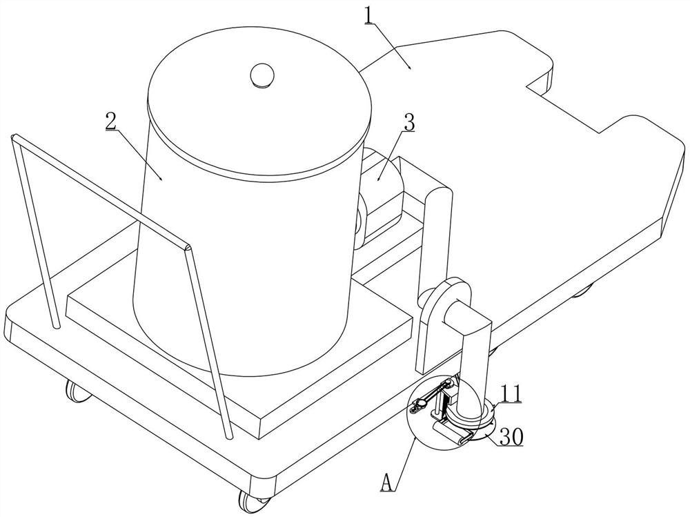
[0041] Embodiment 1, this embodiment provides a kind of asphalt pavement crack filling device, refer to the attached Figure 5 As shown, it includes a trolley 1, and a hot melt box 2 is fixedly installed on the trolley 1 near the handrail, which provides asphalt (asphalt mortar) or joint glue with a temperature that meets the requirements, and there is a paddle-type forced stirring inside. The mixer 43 and grid-type heat conduction coil are used to ensure that the asphalt material is evenly heated. The mixer 43 is driven by a dedicated asphalt mixer 43 drive motor and the drive motor of the asphalt mixing ball is connected to a battery fixed on the cart 1, and the electric There is a controller connected permanently, and the heat transfer oil is indirectly heated by a small gas-fired heating furnace (this is the existing technology, so I won’t go into details here), and the temperature can be automatically adjusted. Thinning), start the agitator 43 to stir the asphalt material...

Embodiment 2

[0044] Embodiment 2, on the basis of embodiment 1, with reference to appended Figure 5 As shown, the conveying system includes an asphalt pump 3 that communicates with the bottom of the hot melt tank 2 and is fixedly installed on the trolley 1, and the asphalt pump 3 is driven by a drive device, which is generally a dedicated drive motor for the asphalt pump 3 drive, And this driving motor is also electrically connected with the controller and connected with the battery, and the asphalt pump 3 is connected with the nozzle 4, and because the melted joint glue has a higher temperature, the general pipeline is easy to be damaged, and in the transmission process If the joint glue melts in it, it will be clogged and the whole device cannot be used. Therefore, we use an electric heating discharge hose for the pipeline connecting the asphalt pump 3, the nozzle 4, and the hot melt tank 2. Electricity is used as the heating condition, and it is equipped with a temperature control sens...

Embodiment 3

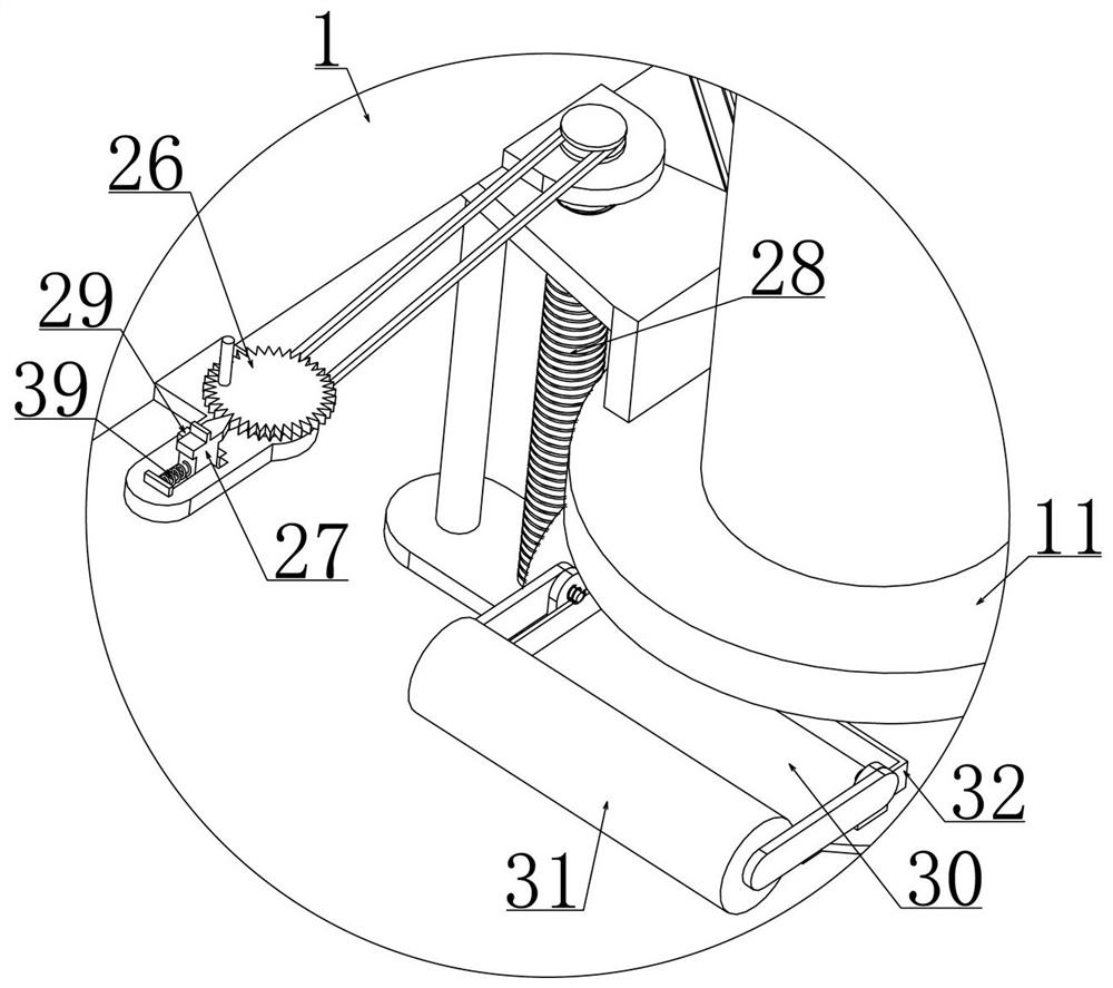
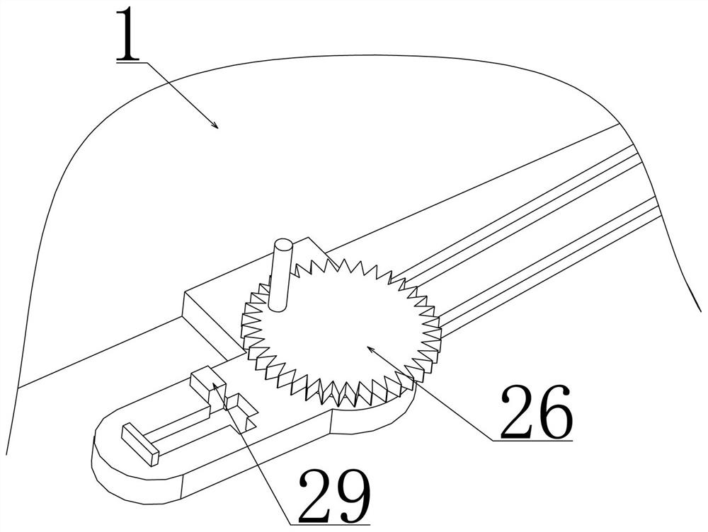
[0046] Embodiment 3, on the basis of embodiment 2, with reference to appended Figure 7 , attached Figure 8 , attached Figure 9 And attached Figure 11 As shown, the flow control device includes an installation cylinder 11 arranged on the upper end of the nozzle 4 and communicated with the electric heating discharge hose, and the top wall of the installation cylinder 11 is rotatably installed with a drive plate 12, and the lower end of the drive plate 12 is provided with six etc. The side-shaped chute 13, in addition, the bottom wall of the installation cylinder 11 is also provided with straight grooves 14 corresponding to the six sides of the chute 13 at equal intervals, and the straight grooves 14 are tangent to the inner wall of the nozzle 4, and the six straight grooves 14 is slidably installed with a flow control plate 15, and each flow control plate 15 is slidably matched with a part of a side of the hexagonal chute 13, so that when we rotate the drive plate 12, the ...


PUM


Abstract

The invention relates to the technical field of road construction, in particular to an asphalt pavement crack filling device, which is characterized in that the deflection direction of a wheel is controlled through the relative movement of a probe, so that a spray head always faces the position of a notch; additionally, the nozzle is provided with a flow control device; along with the change of the groove width, the flow change is controlled in real time, and the crack pouring glue is prevented from overflowing or being not filled.

Description

technical field [0001] The invention relates to the technical field of road construction, in particular to an asphalt pavement crack filling device. Background technique [0002] With the rapid development of my country's social economy, the comprehensive service quality requirements for road traffic are getting higher and higher. However, after a period of use on the road, there will be cracks, potholes, ruts and other diseases on the surface. One of the most common and most likely to occur diseases, the hazards of road cracks not only affect the appearance of the road and driving comfort, but if the cracks are not sealed and repaired in time, it is easier to further expand, making rainwater and other sundries along the road Cracks enter the surface structure and subgrade, causing structural damage to the road, resulting in a decrease in the load-carrying capacity of the road surface, accelerating local or piece-by-piece damage to the road surface, and shortening the service ...

Claims


Application Information

Patent Timeline
Patent Type & Authority Applications(China)
IPC IPC(8): E01C23/09
CPCE01C23/09E01C23/0966E01C23/0973
Inventor 霍延敏李超郉跃芹梁宗梁家红全艳丽姜松朴侯佳璐张志文吴瑞贺
Owner 霍延敏
Why Eureka
Try Eureka