

Method for molding micro-profiled composite joint strips
A forming method and a technology of contact strips, applied in metal processing equipment, metal rolling, metal rolling, etc., can solve the problems of large deviation of welding bars from neutral line, poor downstream welding, waste of precious metals, etc., and solve the problem of welding bars and The effect of offsetting the center line, reducing the adjustment time of the production process, and improving production efficiency
- Summary
- Abstract
- Description
- Claims
- Application Information
AI Technical Summary
Problems solved by technology
Method used
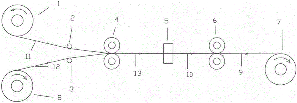
Image

Examples
Embodiment 1
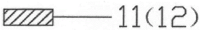
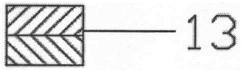
[0042] The AgNi20 round wire is rolled into a square wire with a width of 3.0mm and a thickness of 1.55mm; the CuNi30Fe round wire is rolled into a trapezoidal wire with a width of 3.2mm and a thickness of 1.10mm, and is heated at 880°C, 4m / Hydrogen protection annealing was carried out under the condition of min to reduce the hardness of the matrix material; the two kinds of wires were subjected to ultrasonic cleaning and surface roughness treatment, and then hot-rolled and composited; the composite wires were processed to a square size of 3.0× after mold correction and heat treatment 1.8;
[0043] The AgNi20 / CuNi30Fe with a specification of 3.0×1.8 is preformed into a bimodal composite wire of 2.70×1.42 (such as Figure 8 shown), the specific size is: H 1 = 0.12mm, H 2 = 0.72mm, H 3 = 1.50mm; L 1 =0.60mm, L 2 =1.40mm, L 3 = 2.7mm; shoulder inclination angle β = 12°; finished precious metal thickness 0.70mm, total thickness H 3 =1.18mm, finished product width=3.0mm, fi...
Embodiment 2
[0046]The AgNi10 round wire was rolled into a square wire with a width of 1.20mm and a thickness of 0.76mm, and hydrogen protection annealing was carried out at 780°C and 4m / min; the CuNi30 round wire was rolled into a width of 1.20mm and a thickness of 0.25mm square wire, and under the conditions of 850 ℃, 4m / min hydrogen protection annealing; ultrasonic cleaning of the two kinds of wire, and then roll welding composite; composite wire through mold correction and heat treatment after processing to square Type size 0.96×0.36;
[0047] The AgNi10 / CuNi30 with a specification of 0.96×0.36 is preformed into a bimodal composite filament of 0.93×0.31 (such as Figure 10 shown), the specific size is: H 1 = 0.02mm, H 2 = 0.21mm, H 3 = 0.31 mm; L 1 =0.40mm, L 2 =0.62mm,L 3 = 0.93mm; shoulder inclination angle β = 0°; finished precious metal thickness 0.18mm, total thickness 0.26mm, finished product width = 1.0mm, product inclination angle 0°;
[0048] Continuous forming rolling ...
PUM
| Property | Measurement | Unit |
|---|---|---|
| thickness | aaaaa | aaaaa |
| thickness | aaaaa | aaaaa |
| width | aaaaa | aaaaa |
Abstract
Description
Claims
Application Information