Switch energy storage structure and rotary electrical switch

An electric switch and rotary technology, applied in the field of switches, can solve the problems of performance cost reduction, etc., and achieve the effects of saving floor height, improving utilization rate, and saving diameter

Inactive Publication Date: 2021-10-08
BEIJING GUANGHUA SHITONG TECH
View PDF0 Cites 1 Cited by
  • Summary
  • Abstract
  • Description
  • Claims
  • Application Information

AI Technical Summary

Problems solved by technology

[0003] Looking back at the development of the photovoltaic industry in recent years, although the industry has formulated a standard for the use of DC switches, the research direction of existing technologies is mainly to improve performance and reduce costs. decline

Method used


Image

  • Switch energy storage structure and rotary electrical switch
  • Switch energy storage structure and rotary electrical switch
  • Switch energy storage structure and rotary electrical switch

Examples


Embodiment 1

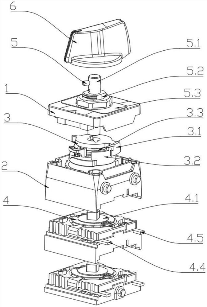
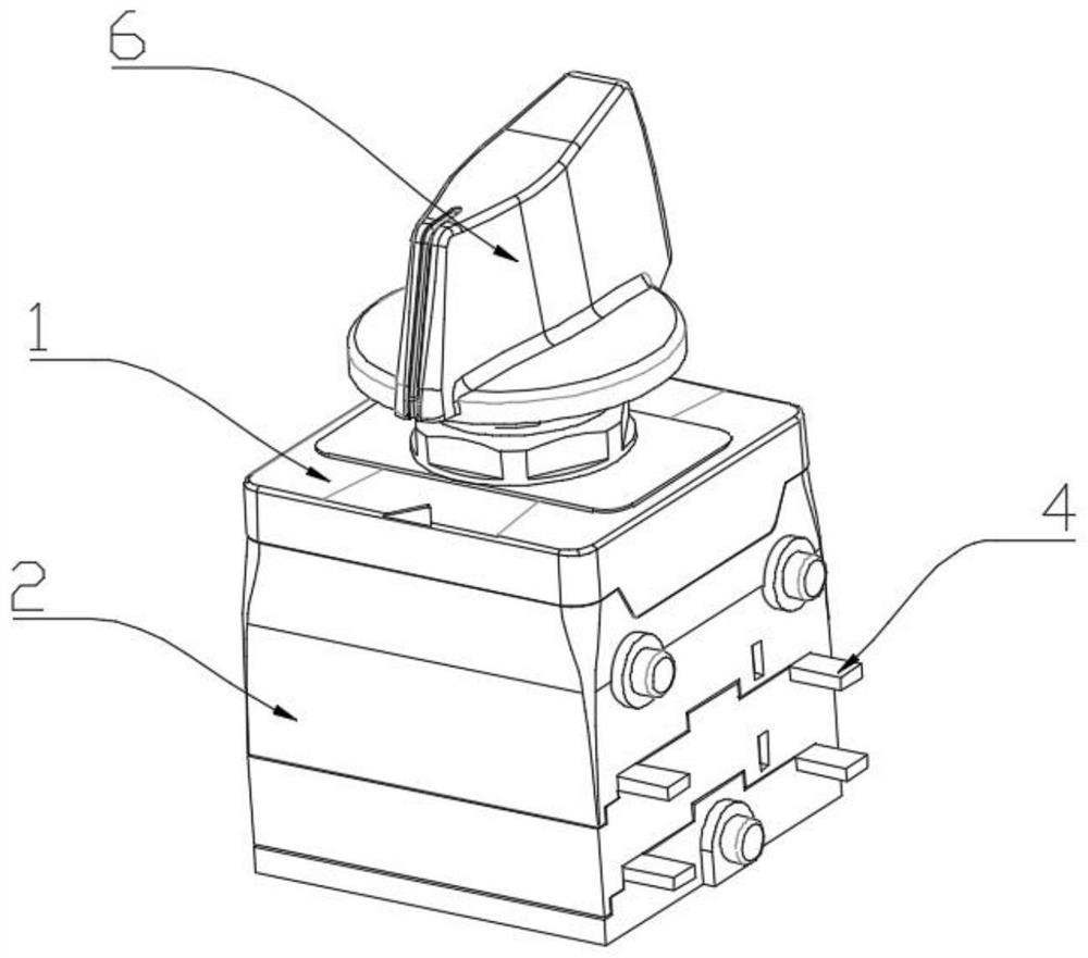
[0058] Join figure 1 , 2 In this embodiment, the present embodiment discloses a rotary electrical switch including a shell cover 1, a multilayer housing 2 disposed at the bottom of the shell cover 1, the multilayer housing, and a multi-layer mounting chamber, multilayer The mounting chamber is provided with an energy storage assembly 3, and the electrically conductive assembly 4, the upper portion of the energy module 3 transmits the operation assembly 6 through the rotation assembly 5 through the housing cover 1, and the lower portion is driven by the conductive assembly 4. The number of conductive assemblies 4 is at least one set, which is disposed in the mounting chamber of the adjacent layer and transmits the connection sequentially.

[0059] Join Figure 7 , 8 The conductive assembly 4 includes a conductive turntable 4.1 and an input static contact 4.2 provided on both sides of the conductive turntable 4.1, and outputs a static contact 4.3, and the conductive turntable 4.1 is ...

Embodiment 2

[0068] Join Figure 9-14 As a preferred embodiment of the present embodiment, the input and static contacts 4.2 are disposed on one end of the conductive turntable 4.1 and at one end of the conductive turntable 4.1 near the wiring outlet, and the input side wiring 4.4 is bent twice. " Z "Dictionary, the other end horizontally exters the outer portion of the housing, the output static contact 4.3 is disposed on one side of the conductive turntable 4.1 and located away from the wiring outlet, the output side wiring 4.5 bends two times. Form a "匚" font, the other ends horizontally exterior, and the input side wiring 4.4 and the output side wiring 4.5 extends out the outer portion of the housing 2 approaches the same plane in parallel to the conductive turntable 4.1; wherein Figure 12-14 In the case, its housing is set to multiple layers.

Embodiment 3

[0070] Join Figure 21-23 As a preferred embodiment of the present embodiment, the input static contacts 4.2 are provided on one end of the conductive turntable 4.1 and located near the wiring outlet of the conductive turntable 4.1, the input side wiring 4.4 is bent to form "L" The word shape and the exterior of the housing, and the plurality of input side wirings 4.2 extending out the outer portion of the housing 2 is in the same straight line, the output static contact 4.3 is disposed on the conductive turntable 4.1 side and located in the conductive turntable 4.1 away from the wiring At one end of the exit, the output side wiring 4.5 is bent twice, and the "匚" font is formed twice, and the one end of the housing extends is vertical surface, and the plurality of output side wirings 4.2 extend outside the housing. The part is in the same line;

[0071] Of the housing is also provided with a terminal block and a terminal cover 8 corresponding to the input side wiring 4.4, the outpu...


PUM


Abstract

The invention discloses a switch energy storage structure and a rotary electrical switch, an energy storage assembly comprises a driving turntable, a rotating seat and an energy storage element arranged in the rotating seat which are sequentially arranged from top to bottom, the rotary electrical switch comprises a shell cover and a multi-layer shell arranged at the bottom of the shell cover, and the interior of the device is divided into multiple layers of mounting cavities by the multi-layer shell; an energy storage assembly and a conductive assembly are arranged in the multiple layers of mounting cavities from top to bottom, the overall size of the switch is small, due to the small size, the size of an inverter is reduced or more lines are output under the same size, and in each implementation mode, the conductive assembly is arranged to be in different bending modes to become the key to meet the requirement for the small size; the projection areas of the conductive turntable and the moving contact rotating plane are overlapped with the input / output wiring conductor, so that the diameter is saved; terminals are arranged in a cross-layer mode, and floor height is saved; and the input side wires and the output side wires are arranged on the same straight line, so that a user can arrange other components on the upper side and the lower side of a wiring plane, and the utilization rate of adjacent spaces is improved.

Description

Technical field [0001] The present invention relates to the field of switches, and more particularly to a switching energy storage structure and a rotary electrical switch. Background technique [0002] With the rapid development of the photovoltaic industry, the safety issues of photovoltaic systems have also gradually been concerned with the masses, and become a hot problem in the industry in recent years. The photovoltaic DC switch is applied to the inverter to control the working state of multiple core components. The reliability of PV DC switches is not only related to the good operation of the entire photovoltaic system, but also related to the stable development of the photovoltaic industry. [0003] Looking back in the development of the photovoltaic industry in recent years, although the industry has developed a standard of DC switches, the existing technical research direction is mainly the promotion of performance and the decline in cost. The present invention will foc...

Claims


Application Information

Patent Timeline
Patent Type & Authority Applications(China)
IPC IPC(8): H01H3/30H01H19/64
CPCH01H3/30H01H19/64Y02E10/56
Inventor 王刚张强张玉霖谢顺亮刘燕兵谷晓春
Owner BEIJING GUANGHUA SHITONG TECH
Why Eureka
Try Eureka