
Chip mounter and chip mounting method

A chip mounter and chip technology, applied in the directions of printed circuits, electrical components, printed circuit manufacturing, etc., can solve the problems of poor chip placement effect and high energy consumption, avoid chip damage, reduce energy consumption, and ensure automatic opening and closing Effect

Active Publication Date: 2021-10-08
SUZHOU SUPERLIGHT MICROELECTRONICS
View PDF9 Cites 1 Cited by
  • Summary
  • Abstract
  • Description
  • Claims
  • Application Information

AI Technical Summary

Problems solved by technology

[0004] The purpose of the present invention is to provide a chip mounter and a chip mounter method, to solve the problem that the chip mounter proposed in the background art has high energy consumption during use and poor chip placement effect

Method used


Image

  • Chip mounter and chip mounting method
  • Chip mounter and chip mounting method
  • Chip mounter and chip mounting method

Examples


Embodiment Construction

[0026] The following will clearly and completely describe the technical solutions in the embodiments of the present invention with reference to the accompanying drawings in the embodiments of the present invention. Obviously, the described embodiments are only some, not all, embodiments of the present invention.

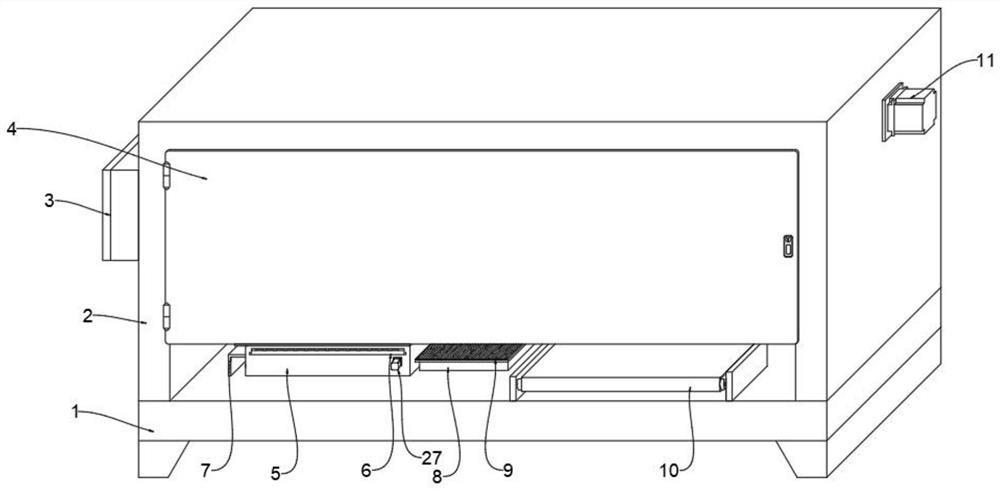
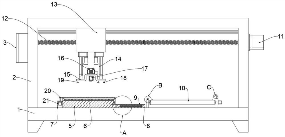
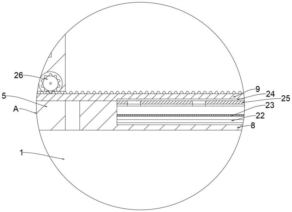
[0027] see Figure 1-5 , an embodiment provided by the present invention: a chip mounter, including a workbench 1, a heating box 8 is installed on the upper end of the workbench 1, the heating box 8 is fixedly connected to the workbench 1, and the lower end of the heating box 8 is installed There is a heating tube 22. Installing the heating tube 22 can preheat the chip so that it can be preliminarily welded on the upper end of the material, preventing the chip from shaking when moving, affecting product quality, increasing the practicability of the device, and ensuring a good placement of the device. Effect, the heating pipe 22 is fixedly connected with the heating b...


PUM


Abstract

The invention discloses a chip mounter and a chip mounting method, relates to the technical field of chip mounting, and aims to solve the problems that an existing chip mounter is high in energy consumption during use and poor in chip mounting effect. A heating box is installed at the upper end of a workbench, a heating pipe is installed at the lower end of the interior of the heating box, an impurity prevention net is installed above the heating pipe, an upper sealing mistaken touch prevention plate is installed above the impurity prevention net, a sealing plate is installed at the upper end of the heating box, and a material support is installed on one side of the upper end of the workbench. Transmission teeth are arranged at the upper end of the sealing plate, a driving gear is installed in the side, close to the heating box, of the material support, a heat preservation motor is installed on the front end face of the material support, and heat reflection aluminum foil layers are installed at the lower end of the sealing plate and the lower end of the upper sealing mistaken touch prevention plate correspondingly.

Description

technical field [0001] The invention relates to the technical field of chip placement, in particular to a chip placement machine and a chip placement method. Background technique [0002] Placement machine: also known as "mounting machine" and "Surface Mount System", in the production line, it is configured after the dispensing machine or screen printing machine, and the surface mount system is mounted by moving the mounting head. A device that accurately places components on PCB pads. It is divided into two types: manual and automatic. The automatic placement machine is a device used to realize high-speed and high-precision automatic placement of components. It is the most critical and complex equipment in the entire SMT production. The placement machine is the main equipment in the SMT production line. The placement machine has developed from an early low-speed mechanical placement machine to a high-speed optical centering placement machine, and has developed into a multi...

Claims


Application Information

Patent Timeline
Patent Type & Authority Applications(China)
IPC IPC(8): H05K3/34H05K13/00H05K13/04H05K13/08
CPCH05K3/341H05K13/0465H05K13/08H05K13/0015
Inventor 高盼盼
Owner SUZHOU SUPERLIGHT MICROELECTRONICS
Learn More