

Water conservancy irrigation device
An irrigation device and water conservancy technology, applied in watering devices, climate change adaptation, gardening, etc., can solve the problems of slowing down the oxidation and corrosion rate of irrigation devices, increasing the service life of devices, reducing irrigation efficiency, etc., and reducing the laying time. , the effect of increasing the degree of sealing and improving the degree of flexibility
- Summary
- Abstract
- Description
- Claims
- Application Information
AI Technical Summary
Problems solved by technology
Method used
Image

Examples
Embodiment 1
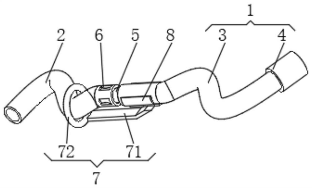
[0034] see Figure 1-4 , the present invention provides a technical solution: a water conservancy irrigation device, comprising a main pipe 1 and a stretching pipe 2, the main pipe 1 and the stretching pipe 2 are alternately connected,
[0035] Main tube 1 has:
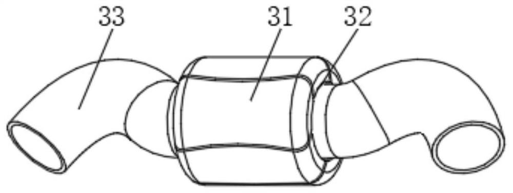
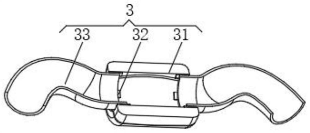
[0036] Intermediate pipe 3, the intermediate pipe 3 has a collapse device 31, the inner wall of the collapse device 31 is provided with a positioning block 32, the side of the positioning block 32 away from the collapse device 31 is provided with an elastic hose 33, and one end of the elastic hose 33 extends to collapse Outside the device 31, the collapsing device 31 and the elastic hose 33 are alternately connected;
[0037] Splicing collar 4, the splicing collar 4 has a main body ring 41, the bottom of the main body ring 41 is made of a magnet, the top of the main body ring 41 is provided with an engaging groove 42, and an opening and closing plate 43 is arranged inside the engaging groove 42.
[0038]Both ends of...
Embodiment 2
[0044] see Figure 1-6 , the present invention provides a technical solution: on the basis of Embodiment 1, the collapse device 31 is composed of arc-shaped single pieces 9 spliced together, the arc-shaped single pieces 9 have a collapse plate 91, and the two sides of the collapse plate 91 are provided with driven plates 92, both sides of the collapse plate 91 are provided with elastic sheets 93, the elastic sheets 93 penetrate the driven plate 92 and extend to the outside of the driven plate 92, and the end of the elastic sheets 93 away from the collapse plate 91 is provided with a baffle 94.
[0045] One side of the collapse plate 91 is provided with an inclined groove 10, and a sliding plate 11 is arranged before the both sides of the inner wall of the inclined groove 10, and the bottom of the sliding plate 11 is uniformly provided with a push plate groove 12, and one side of the inner wall of the push plate groove 12 is connected with The push plate 13 and the inside of ...
PUM
 Abstract
Description
Claims
Application Information