Warning charging wire for automobile charging pile
A technology for car charging and charging lines, applied in electric vehicle charging technology, charging stations, electric vehicles, etc., can solve the problems of easy wear and neglect of charging lines, and reduce the danger of rolling over and tripping pedestrians. Solve the effect of excessive wear and reduce the bending arc
- Summary
- Abstract
- Description
- Claims
- Application Information
AI Technical Summary
Problems solved by technology
Method used
Image
Examples
Embodiment 1
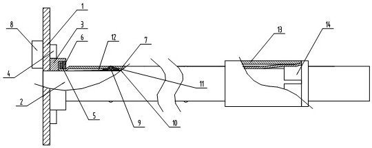
[0020] refer to Figure 1-2 , is a structural schematic diagram of Embodiment 1 of the present invention, a warning charging line for a car charging pile, at least including a body 1 and a charging line 2 connected to the body, including: a positioning ring 3, three connecting plates 4, a snap ring 5, a second A lock nut 6, a protective layer 7 and a prompting portion, the three connecting plates 4 are equidistantly fixed on the outer peripheral surface of the positioning ring 3, and the positioning ring 3 is detachably connected with the shell of the body 1 through the connecting plate 4, so that The charging line 2 is located in the positioning ring 3, the protective layer 7 is arranged on the outer peripheral surface of the charging line 2, the protective layer 7 is a cylindrical mechanism, the snap ring 5 is embedded in the positioning ring 3 side, the One end of the protective layer 7 is clamped between the snap ring 5 and the positioning ring 3, and the positioning ring ...
Embodiment 2
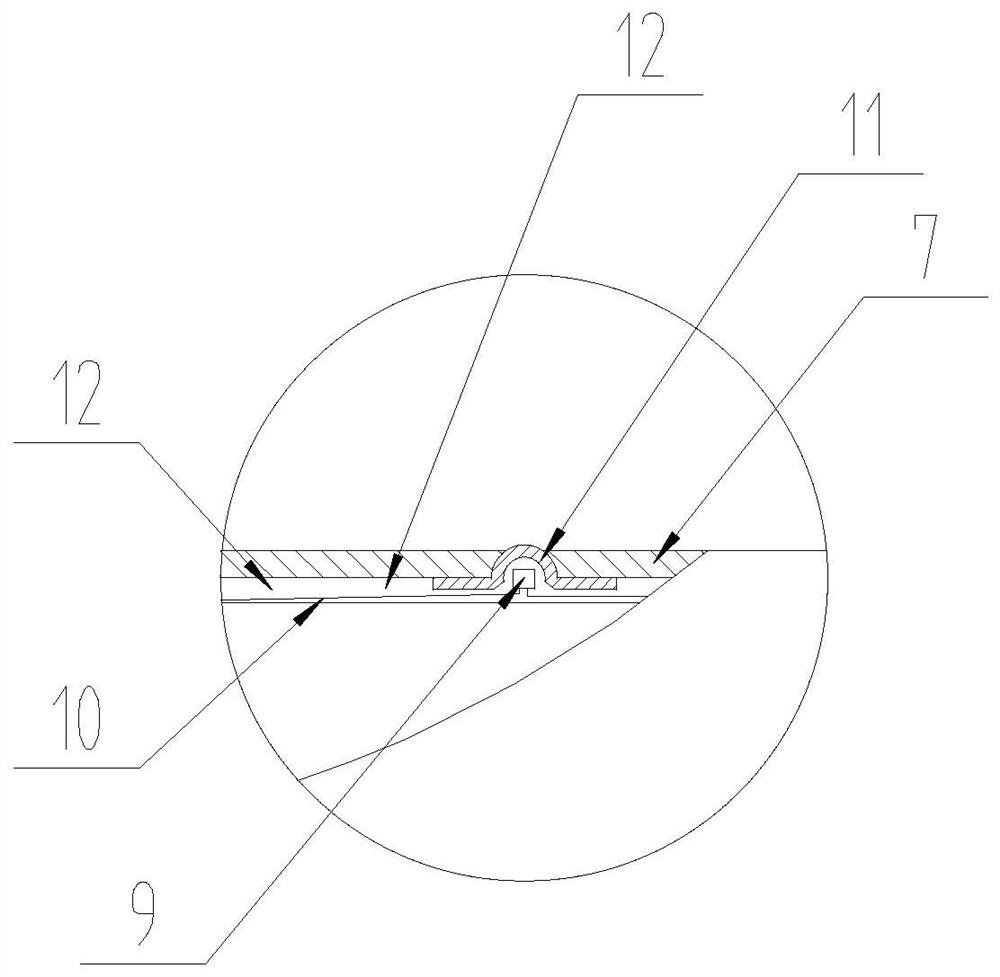
[0023] refer to Figure 1-2 The difference in this embodiment is that the prompting part includes a control module 8, several LED lamps 9 and wires 10, and both sides of the inner circumferential surface of the protective layer 7 are detachably connected to several LED lamps 9 at equidistant distances. The LED lamps 9 on the same side are electrically connected through wires 10, the control module 8 is detachably connected in the body 1, the control module 8 is electrically connected with the LED lamps 9 through wires 10, and the protective layer 7 Be positioned at LED lamp 9 irradiation direction and have indicating hole.
[0024] In actual use: the control module 8 is electrically connected to the body 1, and the LED light 9 is controlled by the control module 8 through the wire 10 to emit a variety of visible colored lights. The light source shines through the indicator hole of the protective layer 7 for warning.
Embodiment 3
[0026] refer to figure 1 , The difference of this embodiment is that a transparent protective cover 11 is embedded in the indicating hole.
[0027] In actual use: the protective cover 11 can protect the LED lamp 9 from wear and tear, thus playing a protective role.
PUM
 Abstract
Description
Claims
Application Information
 - R&D
- Intellectual Property
- Life Sciences
- Materials
- Tech Scout
- Unparalleled Data Quality
- Higher Quality Content
- 60% Fewer Hallucinations
Browse by: Latest US Patents, China's latest patents, Technical Efficacy Thesaurus, Application Domain, Technology Topic, Popular Technical Reports.
© 2025 PatSnap. All rights reserved.Legal|Privacy policy|Modern Slavery Act Transparency Statement|Sitemap|About US| Contact US: help@patsnap.com


