
Illuminator, imaging system and imaging system control method

An imaging system and illuminator technology, applied in lighting devices, non-electric lighting devices, fixed lighting devices, etc., can solve the problems of reduced measurement accuracy, insufficient signal-to-noise ratio, and defocus blur of machine vision systems, and achieve improved imaging Performance and measurement accuracy, resolution of insufficient dynamic range, effects of reducing complexity

Pending Publication Date: 2021-10-12
SHENZHEN INST OF ADVANCED TECH CHINESE ACAD OF SCI +1
View PDF5 Cites 0 Cited by
  • Summary
  • Abstract
  • Description
  • Claims
  • Application Information

AI Technical Summary

Problems solved by technology

However, the layered illumination formed by this technical solution has limited ability to compress the thickness of the optical layer, and the high-magnification imaging depth of field is thinner. Therefore, the optical layer produced by this method is difficult to match the depth of field of the high-magnification imaging system, and there is still a problem of defocus blur
In addition, the illuminator does not consider the dynamic adjustment of light intensity, which leads to insufficient dynamic range of the imaging system, and the imaging is prone to overexposure and insufficient signal-to-noise ratio, which affects the imaging performance
[0005] It can be seen that there are three main technical problems that need to be solved urgently in the existing underwater in-situ optical microscopy and macro imaging technology: 1) Due to the limited depth of field of the imaging system, the target is out of focus and blurred, which in turn leads to the detection and measurement of the target. 2) Due to the unnatural distribution of the target caused by the illumination light, the abundance measurement is inaccurate; 3) Due to the insufficient dynamic range of the imaging system, the target image is overexposed or the signal-to-noise ratio is insufficient, which leads to Machine Vision System Measurement Accuracy Declines

Method used


Image

  • Illuminator, imaging system and imaging system control method
  • Illuminator, imaging system and imaging system control method
  • Illuminator, imaging system and imaging system control method

Examples


Embodiment 1

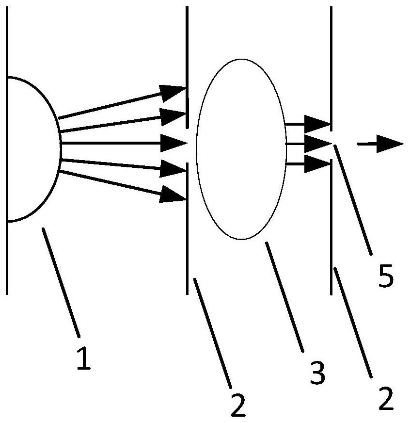
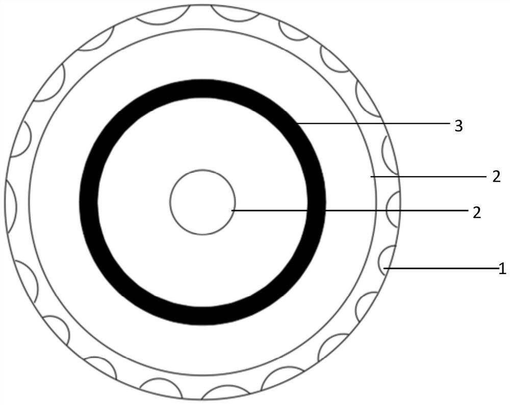
[0091] Embodiment 1 of the present invention proposes an illuminator 100, such as Figure 1-7As shown, it includes: a light source 1, a lens 3, a structural member 4, and one or more diaphragms 2; the lens 3 is used to converge the light emitted by the light source 1; the lens 3 and the diaphragm 2 are all along the The light emitting direction of the light source 1 is set; the structural member 4 is provided with an accommodating chamber for accommodating the light source 1, the lens 3 and the aperture 2; the accommodating chamber is located in the light emitting direction The end is also provided with a light-transmitting window 5 . In this solution, the light source 1 is used to emit light, and the lens 3 and the diaphragm 2 are arranged in the direction of light emission to reduce the emission angle of the light, so as to facilitate the formation of a thinner layer of illuminated light layer, thereby reducing the separation distance. The interference of the out-of-focus b...

Embodiment 2

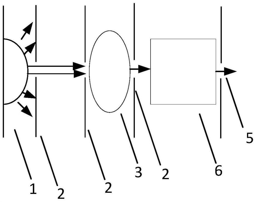
[0110] Embodiment 2 of the present invention also proposes an imaging system 200, such as Figure 19 As shown, it includes: an imaging device, the illuminator described in Embodiment 1; wherein, the light emission direction of the illuminator is perpendicular to the imaging optical axis of the imaging device; the layered illumination light layer produced by the illuminator It matches the field of view and depth of field of the imaging device.

[0111] Based on this, the layered illumination light layer generated by the illuminator matches the field of view and depth of field of the imaging device, which can reduce the proportion of blurred images in the collected images and improve the imaging quality of the imaging system.

[0112] In a specific embodiment, the imaging device further includes: a control module for controlling each of the light sources 1 in the illuminator; the imaging device controls the illuminator to perform frequency flashing light;

[0113] Specifically...

Embodiment 3

[0115] In order to further illustrate the present invention, Embodiment 2 of the present invention also discloses an imaging system control method, which controls the illumination of the illuminator through the control module in the imaging system described in Embodiment 2, specifically, including the following steps:

[0116] Step 101, adopt the default mode to perform the imaging operation to generate an image; therefore, step 101 specifically includes the following steps: controlling the illuminator to perform strobe lighting with the default light intensity and default frequency through the control module, and at the same time according to the default frame The imaging operation is carried out at a certain rate to acquire images; the default frequency is the same as the default frame rate; the frame rate of the imaging operation is the same as the frequency of the strobe lighting; the default light intensity is between the weakest light intensity and the strongest light inte...


PUM


Abstract

The invention provides an illuminator, an imaging system and an imaging system control method, and the illuminator comprises a light source, a lens, a structural member, and one or more diaphragms. The lens is used for converging light rays emitted by the light source; the lens and the diaphragm are arranged along the light emitting direction of the light source; the structural member is provided with an accommodating cavity for accommodating the light source, the lens and the diaphragm; and a light-transmitting window is arranged at the end part of the accommodating cavity in the light emitting direction. Through the lens and the diaphragm in the illuminator in the scheme, the light emission angle of the light source in the illuminator is limited, so that a layered illumination light layer can be generated, the interference of a fuzzy background on a clear foreground in a subsequent imaging process is reduced, and the proportion of an out-of-focus fuzzy image in a generated image is reduced.

Description

technical field [0001] The invention relates to the field of illuminating devices, in particular to an illuminator, an imaging system and a control method for the imaging system. Background technique [0002] Underwater tiny organisms and particulates are important components of the water environment. The study of these tiny organisms and particulates has important scientific significance and application value for water environment science, microbiology, marine science, ecology and other disciplines. The underwater optical microscopy and macro imaging method can obtain non-contact and fast high-quality particle images, and then achieve more accurate measurement, identification and statistics. It is an important means to obtain and study underwater microbiological and particle information. [0003] Currently there are some systems or methods for underwater imaging and lighting, for example, patent WO2016 / 048851 describes a continuous particle imaging and classification system...

Claims


Application Information

Patent Timeline
IPC IPC(8): F21S8/00F21V5/04F21V19/00F21V1/00
CPCF21S8/00F21V5/04F21V19/00F21V1/00Y02B20/40
Inventor 陈涛章逸舟陈良培刘鹏李剑平
Owner SHENZHEN INST OF ADVANCED TECH CHINESE ACAD OF SCI
Learn More