

Method for improving wear resistance of hardware stamping die
A stamping die and wear resistance technology, applied in the field of improving the wear resistance of metal stamping dies, can solve the problems of high wear rate of the stamping head, difficult to accurately control the surface hardening technology, hot cracks, etc., so as to improve the impact resistance and improve the resistance Abrasiveness, the effect of improving wear resistance and strength
- Summary
- Abstract
- Description
- Claims
- Application Information
AI Technical Summary
Problems solved by technology
Method used
Image

Examples
Embodiment 1
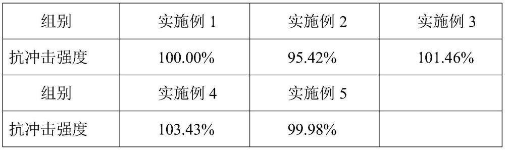
[0037] In the stamping die provided by Example 1 of the present invention, the wear-resistant part material of the stamping head includes in parts by weight: 65 parts of cast tungsten carbide with a particle size of 20 to 200 mesh, 8 parts of cast stone powder, 8 parts of china clay, and binder 5 parts, 4 parts sodium silicate. Among them, 25 parts of cast tungsten carbide with a particle size of 20-40 mesh, 10 parts of cast tungsten carbide with a particle size of 40-80 mesh, 10 parts of cast tungsten carbide with a particle size of 80-120 mesh, 10 parts of cast tungsten carbide with a particle size of 120-160 mesh, 10 parts of cast tungsten carbide with a particle size of 160-200 mesh.
[0038] The stamping head provided by embodiment 1 is prepared through the following steps:
[0039] S1: Mix 65 parts of cast tungsten carbide with a particle size of 20 to 200 meshes, 8 parts of cast stone powder, and 8 parts of china clay. After stirring, carry out 1-3 hours of trapping, t...
Embodiment 2
[0051] In the stamping die provided by Example 2 of the present invention, the wear-resistant part material of the stamping head includes in parts by weight: 60 parts of cast tungsten carbide with a particle size of 20 to 200 meshes, 3 parts of cast stone powder, 6 parts of china clay, and binder 3 parts, 3 parts sodium silicate. Among them, 10 parts of cast tungsten carbide with a particle size of 20-40 mesh, 10 parts of cast tungsten carbide with a particle size of 40-80 mesh, 15 parts of cast tungsten carbide with a particle size of 80-120 mesh, 10 parts of cast tungsten carbide with a particle size of 120-160 mesh, 15 parts of cast tungsten carbide with a particle size of 160-200 mesh.
[0052] The stamping head provided by embodiment 2 is prepared through the following steps:
[0053] S1: 60 parts of cast tungsten carbide with a particle size of 20 to 200 meshes, 3 parts of cast stone powder, and 6 parts of china clay, mix thoroughly, stir for 1-3 hours, then add 3 parts...
Embodiment 3
[0065] In the stamping die provided by Example 3 of the present invention, the wear-resistant part material of the stamping head includes in parts by weight: 62 parts of cast tungsten carbide with a particle size of 20 to 200 meshes, 5 parts of cast stone powder, 8 parts of china clay, and binder 5 parts, 5 parts sodium silicate. Among them, 12 parts of cast tungsten carbide with a particle size of 20-40 mesh, 10 parts of cast tungsten carbide with a particle size of 40-80 mesh, 15 parts of cast tungsten carbide with a particle size of 80-120 mesh, 10 parts of cast tungsten carbide with a particle size of 120-160 mesh, 15 parts of cast tungsten carbide with a particle size of 160-200 mesh.
[0066] The stamping head provided by embodiment 3 is prepared through the following steps:
[0067] S1: Mix 62 parts of cast tungsten carbide with a particle size of 20 to 200 meshes, 5 parts of cast stone powder, and 8 parts of china clay, mix thoroughly, stir for 1-3 hours, then add 5 p...
PUM
| Property | Measurement | Unit |
|---|---|---|
| Granularity | aaaaa | aaaaa |
| Granularity | aaaaa | aaaaa |
| Granularity | aaaaa | aaaaa |
Abstract
Description
Claims
Application Information