Feedforward timing recovery method and system suitable for high-speed spaceborne optical communication

A timing recovery and optical communication technology, which is applied in the modulation carrier system, transmission system, multi-frequency code system, etc., can solve the problems of poor timing recovery performance, increased feedback delay, and decreased accuracy of sampling clock offset estimation. Achieve the effects of ensuring accuracy and stability, avoiding symbol errors, and improving estimation accuracy

Active Publication Date: 2021-10-15
XIAN INSTITUE OF SPACE RADIO TECH
View PDF5 Cites 0 Cited by
  • Summary
  • Abstract
  • Description
  • Claims
  • Application Information

AI Technical Summary

Problems solved by technology

Among them, the commonly used feedback recovery method is to use the detected timing error signal in the current observation data block to drive the digital interpolator to realize the timing recovery of the next observation data block. Due to the adoption of the feedback mechanism, the timing error extraction of this method has a certain delay In the case of high-speed spaceborne optical communication, with the increase of the number of parallel processing channels, the feedback delay increases, resulting in poor timing recovery performance, unable to resist large timing errors
The feed-forward method uses the current observation data block to estimate the offset of the sampling clock, and then realizes the timing recovery of the current observation data block through a digital interpolator. This method has good real-time performance, fast convergence speed, and is easier to process in parallel. Under the condition of noise ratio, the accuracy of sampling clock offset estimation decreases, and the timing recovery performance deteriorates
In addition, in actual spaceborne optical communication applications, the receiving AD sampling clock frequency is usually slightly higher than twice the communication symbol rate, how to accurately remove the redundant sampling points caused by timing errors is also the difficulty of this method

Method used


Image

  • Feedforward timing recovery method and system suitable for high-speed spaceborne optical communication
  • Feedforward timing recovery method and system suitable for high-speed spaceborne optical communication
  • Feedforward timing recovery method and system suitable for high-speed spaceborne optical communication

Examples


Embodiment

[0111] With the QPSK modulation mode (applicable scene is not limited to QPSK modulation mode), the receiving end is sampled with a sampling rate higher than about 2 times symbol speed to sample the input signal, and the number of sampling output is N (n = 32, 64, 128, 256, 512, 1024 Optional), then the sampling output signal at the K time is:

[0112] X k = {X k,1 , X k,2 , ... x k,N } = {X (k-1)*N+1 , X (k-1)*N+2 , ... x k*N }

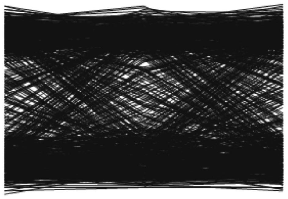
[0113] Due to the timing error, the reception sample is not performed at the best time, the corresponding received signal constellation diagram and the eye diagram are respectively figure 2 , image 3 As shown, the transmitted symbol information cannot be restored correctly. Timer recovery processing is required.

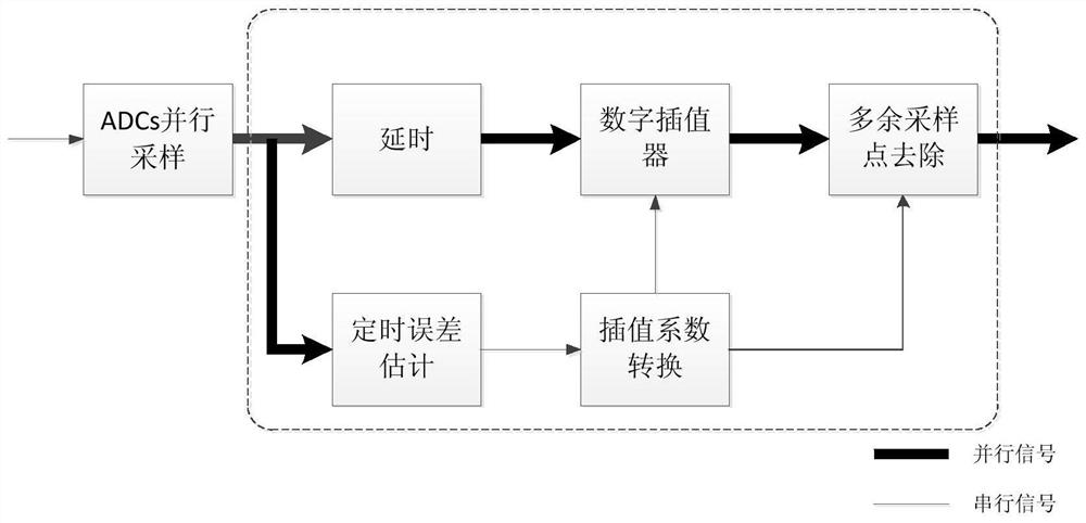
[0114] The steps of the methods of the invention are as follows:

[0115] (1) K Mometown Sampling Output Observation Data Block X k , Calculate the timing error estimate according to the formula:

[0116]

[0117]

[0118] (2) Timer error b...


PUM


Abstract

A feedforward timing recovery method suitable for high-speed spaceborne optical communication comprises the following steps: (1) sampling a received signal at a frequency higher than two times of a symbol rate, and estimating a timing error, wherein the timing error refers to the relative time offset of the actual sampling point relative to the ideal sampling point; (2) determining an interpolation coefficient mu k of a digital interpolator according to the timing error estimated in the step (1); (3) carrying out digital interpolation processing on the sampling signal block according to the interpolation coefficient mu k obtained in the step (2); (4) removing redundant sampling points in the data after interpolation processing to complete feedforward timing recovery. According to the invention, high-precision and high-stability feed-forward timing recovery can be realized under a double symbol rate sampling receiving system, and the method is more suitable for a high-speed satellite-borne optical communication system with resource shortage and limitation.

Description

Technical field [0001] The present invention is in high-speed satellite reception carrier BACKGROUND optical communication, and more particularly to a method and feedforward timing recovery system suitable for high speed optical communications onboard. Background technique [0002] In high-speed optical communications onboard process, different sources causes the transceiver end of certain clock timing error transceiver, requires that the receiving end timing recovery received samples at the optimum moment. The timing recovery processing algorithm structure can be divided into two types: a feedback and a feedforward recovery methods recovery methods. Wherein the method is used to restore a feedback current detected by the timing recovery block, the observed data within a timing error signal drives a digital interpolator block observations realized the next, thanks to a feedback mechanism, a method of extracting the timing error has a certain delay resistance, high-speed optical c...

Claims


Application Information

Patent Timeline
Patent Type & Authority Applications(China)
IPC IPC(8): H04B10/118H04L27/26
CPCH04B10/118H04L27/2671
Inventor 孙晶郭精忠张建华汪滴珠兰枫陈翔幺周石
Owner XIAN INSTITUE OF SPACE RADIO TECH
Why Eureka
Try Eureka