Composite structure and manufacturing method therefor
A structure and a single technology, applied to the superstructure, the connection between the subassemblies of the superstructure, and other household appliances, etc., can solve the problems of low strength, difficulty in application, increase in operating procedures or manufacturing costs, and achieve simplified shapes Effect
- Summary
- Abstract
- Description
- Claims
- Application Information
AI Technical Summary
Problems solved by technology
Method used
Image
Examples
no. 1 approach
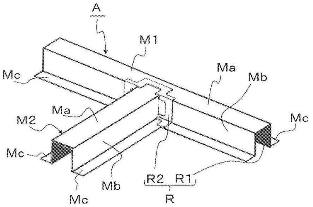
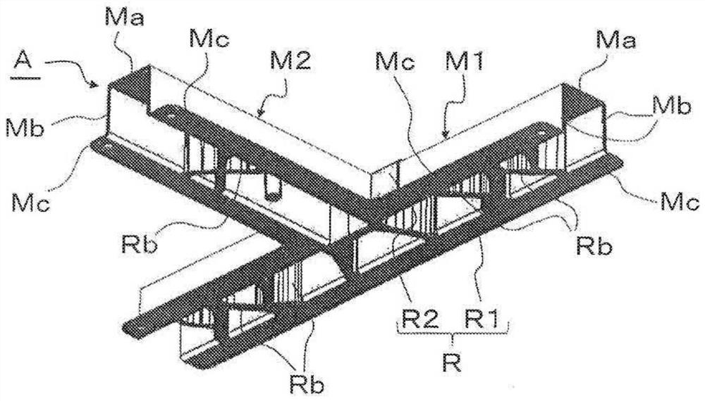
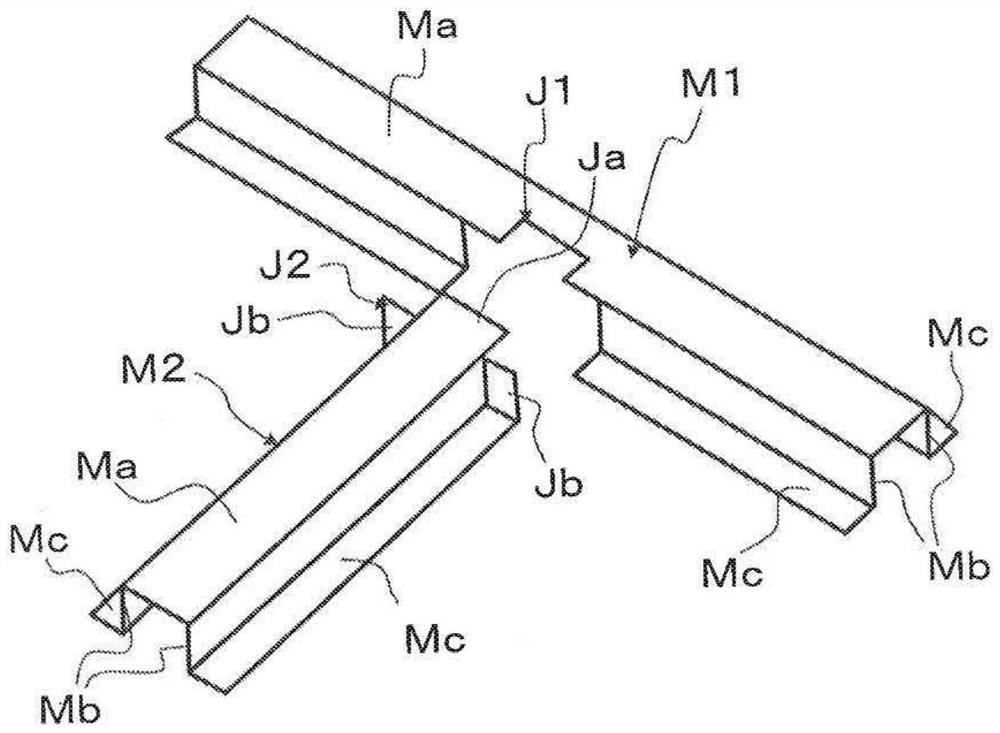
[0045] Figure 1 to Figure 6 It is a figure explaining the 1st Embodiment of the composite structure of this invention. In addition, in each of the following embodiments, for the sake of convenience, the up-down, left-right, and up-down relationships of the constituent parts will be described in the postures shown in the drawings. Therefore, the up, down, left, and right relationships of the constituent parts are not limited to the postures in actual use.
[0046] figure 1 and figure 2 The shown composite structure A includes a plate-shaped first metal member M1, a plate-shaped second metal member M2, and a resin member R integrating the first and second metal members M1 and M2. The resin member R has: a first resin layer R1 covering one main surface of each of the first and second metal members M1, M2; and a first resin layer R1 covering the other of the first and second metal members M1, M2 The second resin layer R2 on the main surface.
[0047] The main surface refers...
no. 2 approach
[0065] Figure 7 and Figure 8 The shown composite structure A has a plate-shaped first metal member M1, a plate-shaped second metal member M2, and a resin member R integrating the first and second metal members M1 and M2. Moreover, in the composite structure A, the resin member R has the connection part R3 which connects the 1st resin layer R1 and the 2nd resin layer R2. In the composite structure A of this embodiment, a gap S is provided between the first and second metal members M1 , M2 , and a connecting portion R3 is formed in the gap S. As shown in FIG.
[0066] The composite structure A having the above-mentioned structure obtains the resin part R in which the first and second resin layers R1, R2 are integrated through the connection part R3, and by securing the first and second metal parts M1, M2 and the resin part R largely The contact area can further increase the strength and rigidity of the joint between the two metal parts M1 and M2.
[0067] In addition, in th...
no. 3 approach
[0075] Figure 12 The composite structure A shown is the same as the first embodiment, and one of the first and second metal members M1, M2 (the first metal member M1) has a The junction J2 of M2) is the junction J1 formed correspondingly to the shape of the end. In addition, in the first embodiment, the structure in which the end portion of the second metal member M2 is joined in the middle of the side portion Mb of the first metal member M1 has been described, but in this embodiment, the side of the first metal member M1 The end of the portion Mb engages the end of the second metal member M2.
[0076] In addition to the above-mentioned composite structure A having the same effect as the previous embodiment, the two joint parts J1, J2 are a combination of three-dimensional shapes, so the joint force can be improved, and the transmission of force can be dispersed to achieve further improvement in strength and rigidity. improve.
PUM
 Abstract
Description
Claims
Application Information
 - R&D
- Intellectual Property
- Life Sciences
- Materials
- Tech Scout
- Unparalleled Data Quality
- Higher Quality Content
- 60% Fewer Hallucinations
Browse by: Latest US Patents, China's latest patents, Technical Efficacy Thesaurus, Application Domain, Technology Topic, Popular Technical Reports.
© 2025 PatSnap. All rights reserved.Legal|Privacy policy|Modern Slavery Act Transparency Statement|Sitemap|About US| Contact US: help@patsnap.com


