
A precision numerical control machine tool for hardware processing

A precision numerical control and hardware technology, applied in metal processing machinery parts, metal processing equipment, manufacturing tools, etc., can solve problems such as waste of resources, collision between milling cutters and splints, and high consumption of lubricating oil, saving production costs, Smooth processing and solid-liquid separation

Active Publication Date: 2022-06-03
安庆皖台精密机械有限公司
View PDF8 Cites 0 Cited by
  • Summary
  • Abstract
  • Description
  • Claims
  • Application Information

AI Technical Summary

Problems solved by technology

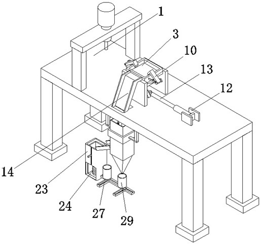
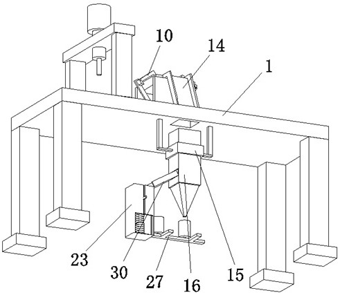
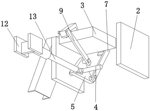
[0003] When machining metal hardware on a machine tool, due to the excessive hardness of the metal, it is often necessary to add lubricating oil from time to time to ensure the lubrication between the milling cutter and the hardware, and the processing debris of the hardware will condense with the lubrication, It is difficult to remove, which will affect the processing of hardware parts, and this method consumes a lot of lubricating oil. There is no additional structure for collecting lubricating oil on the existing machine tools, and the lubricating oil cannot be reused, which will cause waste of resources and increase Production cost. On the other hand, the way of fixing parts of traditional machine tools is to use splints and bolts to fix the parts. This fixing method will cause the splint to be on the upper surface of the part, which will easily cause the milling cutter and the splint to collide with each other, resulting in broken tools. Problems arise, and the use effect is not ideal, so a precision CNC machine tool for hardware processing is proposed here to solve the above problems

Method used


Image

  • A precision numerical control machine tool for hardware processing
  • A precision numerical control machine tool for hardware processing
  • A precision numerical control machine tool for hardware processing

Examples


Embodiment Construction

[0022] The technical solutions in the embodiments of the present invention will be clearly and completely described below with reference to the accompanying drawings in the embodiments of the present invention. Obviously, the described embodiments are only a part of the embodiments of the present invention, but not all of the embodiments.

[0023] see figure 1 , figure 2 , image 3 , Figure 4 , Figure 5 , Image 6 , Figure 7, the present invention provides a technical solution: a precision CNC machine tool for hardware processing, including a processing table 1, through the through groove opened on the front side of the upper surface of the processing table 1, the hardware debris can be easily introduced into the In the filter box 16, it plays the role of preparing for the solid-liquid separation of the metal chips condensed with the lubricating oil. A fixed table 3 is fixedly installed on the upper side, a rotating shaft 4 is movably sleeved in the middle part of th...


PUM


Abstract

The invention discloses a precision numerical control machine tool for hardware processing, relates to the technical field of numerical control machine tools, and specifically relates to a precision numerical control machine tool for hardware processing, including a processing table, and the middle part of the upper surface of the processing table is fixedly installed There is a first mounting plate, a fixed platform is fixedly installed on the upper side of the cavity of the first mounting plate, and a rotating shaft is movably socketed in the middle of the cavity of the first mounting plate. The precision CNC machine tool for hardware processing can filter the lubricating oil on the hardware debris through the filter plate, guide the lubricating oil to the oil guide funnel, and finally concentrate it in the oil holding cup, and with the hardware debris More and more accumulated on the filter plate, the weight is getting bigger and bigger, which will make the moving connecting rod squeeze the first limit spring and start to descend, and finally be guided to the bin, and concentrated in the storage box, which can effectively realize Solid-liquid separation realizes the reuse of lubricating oil, which can save production costs.

Description

technical field [0001] The invention relates to the technical field of numerical control machine tools, in particular to a precision numerical control machine tool for processing hardware. Background technique [0002] A machine tool refers to a machine that makes a machine, also known as a work machine or a tool machine. It is habitually referred to as a machine tool. It is generally divided into metal cutting machine tools, forging machine tools and woodworking machine tools. , as well as casting, forging, welding, stamping, extrusion, etc., but for parts with high precision and fine surface roughness requirements, they generally need to be processed by cutting on the machine tool. Machine tools are in the modernization of the national economy. The lathe is a machine tool that mainly uses turning tools to turn the rotating workpiece. On the lathe, drills, reaming drills, reamers, taps, dies and knurling tools can also be used for corresponding processing. , Lathes are mai...

Claims


Application Information

Patent Timeline
Patent Type & Authority Patents(China)
IPC IPC(8): B23Q3/06B23Q11/12B23Q11/00
CPCB23Q3/06B23Q11/12B23Q11/00Y02P70/10
Inventor 林海燕徐建明朱胜文
Owner 安庆皖台精密机械有限公司
Learn More