
Circuit board transmission device and circuit board transmission control method thereof

A transmission device, circuit board technology, applied in the direction of transportation and packaging, conveyors, conveyor objects, etc., can solve the problems of increasing process complexity, pollution, easy to drop boards, etc., to ensure the appearance and quality, to ensure the overall appearance, The effect of not easily falling off the board

Active Publication Date: 2021-10-19
东莞市多普光电设备有限公司
View PDF7 Cites 0 Cited by
  • Summary
  • Abstract
  • Description
  • Claims
  • Application Information

AI Technical Summary

Problems solved by technology

[0006] (1) Vacuum suction is used to transfer the circuit board (PCB), but it is easy to drop the board, and the requirement for the edge material is generally 6-10mm or more, which is contradictory to the substrate utilization rate of the circuit board (PCB) factory, and There is still a risk of contamination to the effective area of ​​the circuit board (PCB);
[0007] (2) Using the plywood edge method can reduce the risk of board falling, but the substrate edge material is also required to be more than 6-10mm, and the table must be avoided, which increases the complexity of the process

Method used


Image

  • Circuit board transmission device and circuit board transmission control method thereof
  • Circuit board transmission device and circuit board transmission control method thereof
  • Circuit board transmission device and circuit board transmission control method thereof

Examples


Embodiment Construction

[0038] In order to further illustrate the technical means and functions adopted by the present invention to achieve the intended purpose, the specific implementation modes of the present invention will be described in detail below in conjunction with the accompanying drawings and preferred embodiments.

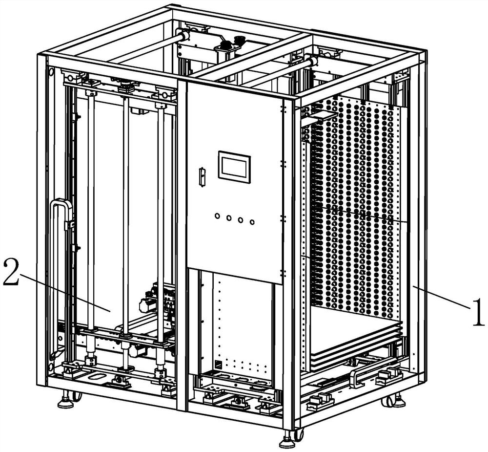
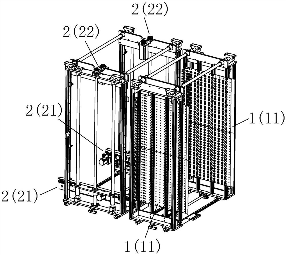
[0039] Please refer to figure 1 and figure 2 , The embodiment of the present invention provides a circuit board transmission device, including a controller, a circuit board temporary storage mechanism 1 electrically connected to the controller, and a circuit board lifting type grabbing and conveying mechanism 2 electrically connected to the controller. The circuit board temporary storage mechanism 1 is used to temporarily store several circuit boards, and the circuit board lifting type grabbing and conveying mechanism 2 is used to grab the circuit boards on the circuit board temporary storage mechanism 1 and transfer them backwards to complete the automatic conveying process ...


PUM


Abstract

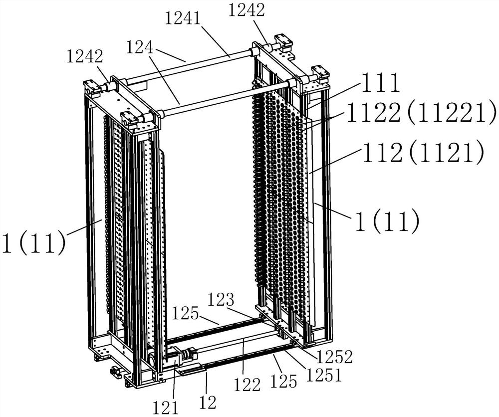
The invention discloses a circuit board transmission device which comprises a controller, a circuit board temporary storage mechanism and a circuit board lifting type grabbing and conveying mechanism, the circuit board temporary storage mechanism and the circuit board lifting type grabbing and conveying mechanism are electrically connected to the controller, the circuit board temporary storage mechanism comprises two sets of temporary storage bearing frame assemblies which are oppositely arranged, each temporary storage bearing frame assembly comprises a first longitudinal installation support and a temporary storage bearing plate structure, wherein the temporary storage bearing plate structure comprises a longitudinal base plate arranged on the side face of the first longitudinal installation support and a plurality of rows of bearing shaft structures arranged on the longitudinal base plate, and each bearing shaft structure is composed of a plurality of bearing shafts rotationally arranged on the longitudinal base plate. The circuit board lifting type grabbing and conveying mechanism comprises two sets of grabbing and conveying assemblies arranged oppositely and two sets of lifting driving assemblies, and each grabbing and conveying assembly comprises a grabbing structure, a conveying driving structure arranged on an installation side plate and a plurality of conveying rollers arranged on the installation side plate and connected to the conveying driving structure. The invention further discloses a circuit board transmission control method based on the circuit board transmission device.

Description

technical field [0001] The invention relates to a circuit board transmission device, in particular to a circuit board transmission device and a circuit board transmission control method thereof. Background technique [0002] In the existing circuit board transmission equipment, once a certain mechanism in the equipment fails, it will directly affect the normal operation of the front mechanism or the rear mechanism, resulting in a decrease in the working efficiency of the entire equipment. [0003] In the traditional circuit board (PCB) manufacturing process, multiple structural surfaces in the equipment will contact multiple areas on the circuit board, especially the active area (that is, the area where the circuit is formed), resulting in damage to the active area on the circuit board. Great impact, for example, the surface of the circuit board is scratched, and the appearance does not meet the requirements; the circuit on the effective area of ​​the circuit board is damage...

Claims


Application Information

Patent Timeline
Patent Type & Authority Applications(China)
IPC IPC(8): B65G47/74B65G47/24B65G47/90B65G13/06
CPCB65G47/74B65G47/24B65G47/901B65G13/06B65G2201/022
Inventor 郑超杰邱田生詹泽军李诚黄启兵
Owner 东莞市多普光电设备有限公司
Learn More