Preparation device and method of amorphous alloy component, amorphous alloy component and electronic equipment

A technology for amorphous alloys and preparation devices, which is applied in the preparation of amorphous alloys and its application fields, can solve problems such as high cost and low yield, and achieve the effects of reducing production costs, improving yield, and improving surface quality and performance

Active Publication Date: 2021-10-22
HUAWEI TECH CO LTD
View PDF7 Cites 2 Cited by
  • Summary
  • Abstract
  • Description
  • Claims
  • Application Information

AI Technical Summary

Problems solved by technology

[0006] The purpose of this application is to provide a preparation device, preparation method, amorphous alloy member and electronic equipment of an amorphous alloy component, so as to alleviate the problems of high cost and low yield in the preparation process of existing amorphous alloy products, Can overcome the problems in the above-mentioned background technology or at least partially solve the above-mentioned technical problems

Method used


Image

  • Preparation device and method of amorphous alloy component, amorphous alloy component and electronic equipment
  • Preparation device and method of amorphous alloy component, amorphous alloy component and electronic equipment
  • Preparation device and method of amorphous alloy component, amorphous alloy component and electronic equipment

Examples


preparation example Construction

[0079] The preparation device of the amorphous alloy component uses the centrifugal effect of the centrifugal casting arm and the forming mold to rotate at a high speed and the pressure of the high-pressure inert gas chamber to release the high-speed flowing gas to quickly inject the melt into the forming mold, and finally obtain the amorphous alloy product , such as amorphous Cato. The preparation device combines the pressure effect of high-pressure inert gas with centrifugal casting technology to realize the molding of castings. Compared with traditional amorphous alloy forming equipment, it improves the filling capacity and feeding capacity of metal melt on the one hand, and improves the The surface quality of the casting, the performance of the product is better, the structure is more compact, and the yield rate of the product is improved. On the other hand, the clever use of centrifugal force and pressure difference to achieve rapid cooling ensures that the product is an a...

Embodiment 1

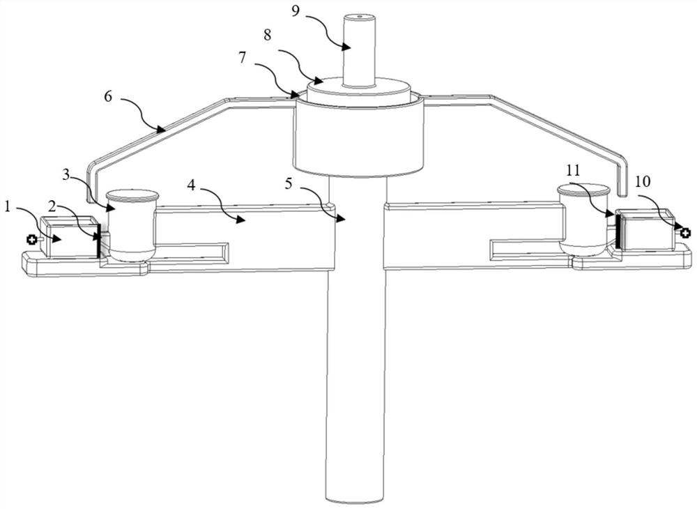
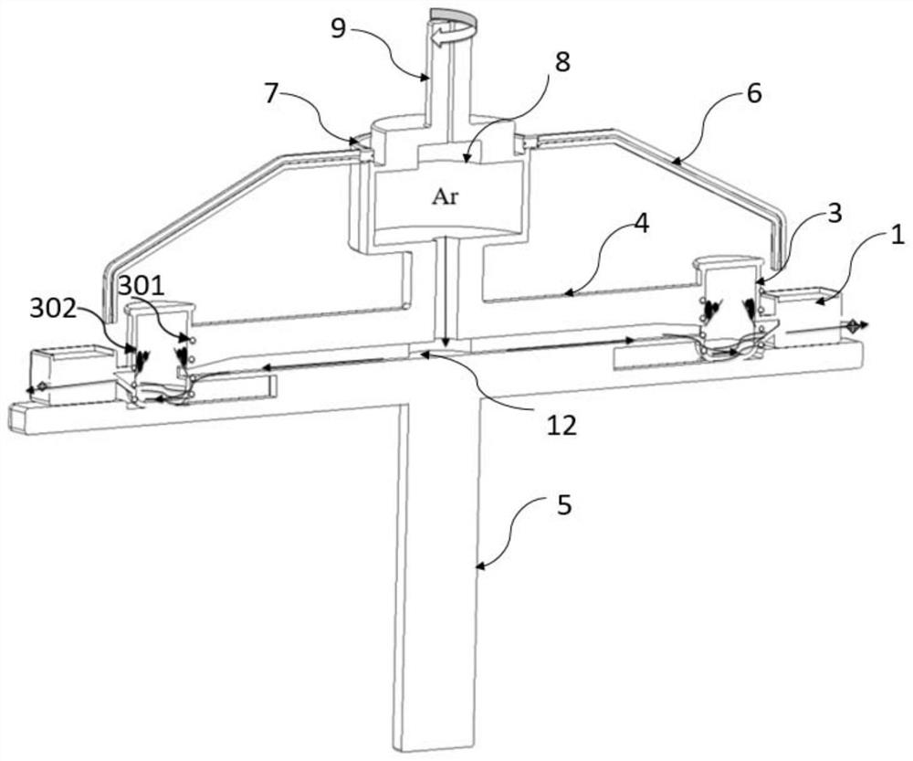
[0161] Such as figure 1 and figure 2 As shown, a preparation device for an amorphous alloy component includes a centrifugal mechanism, a melting and forming mechanism, an inert gas mechanism and a cooling mechanism.

[0162]Among them, the centrifugal mechanism includes a centrifugal casting arm 4 and a centrifugal shaft 5. The bottom end of the centrifugal shaft 5 is connected to the centrifugal casting machine, and the centrifugal casting machine is used to drive the centrifugal shaft 5 to rotate. The top of the centrifugal shaft 5 is connected to the inert gas chamber 8. The centrifugal casting The arm 4 is connected to the middle and upper part of the centrifugal shaft 5, and both the centrifugal casting arm 4 and the centrifugal shaft 5 have an inert gas channel 12 for the inert gas to flow through.

[0163] The inert gas mechanism includes a high-pressure inert gas chamber 8, an inert gas pipe 9, a one-way gas stop valve 10, and an inert gas supply device; the inert ga...

Embodiment 2

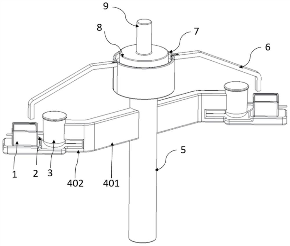
[0167] Such as image 3 As shown, a preparation device for an amorphous alloy component differs from Example 1 in the centrifugal casting arm.

[0168] In this embodiment, the main body of the centrifugal casting arm 4 is bent, including a first bent portion 401 and a second bent portion 402 connected to each other, wherein one end of the first bent portion 401 can be connected to the centrifugal shaft 5, The crucible 3 and the forming mold 1 are arranged on the second bending part 402 , and the bending angle between the first bending part 401 and the second bending part 402 may be 45°.

[0169] During the centrifugal casting process, the pouring direction of the metal molten liquid is 45° to the centrifugal shaft. After a lot of experiments, it is found that when the pouring angle is adjusted to 45°, the amorphous alloy structural parts can obtain better surface quality and forming accuracy.


PUM

PropertyMeasurementUnit
lengthaaaaaaaaaa
angleaaaaaaaaaa
angleaaaaaaaaaa

Abstract

The invention relates to the technical field of preparation and application of amorphous alloy, and particularly relates to a preparation device and method of an amorphous alloy component, the amorphous alloy component and electronic equipment. The preparation device of the amorphous alloy component comprises a centrifugal mechanism, a smelting forming mechanism, an inert gas mechanism and a cooling mechanism, the centrifugal mechanism comprises a centrifugal rotating shaft and a centrifugal casting arm, and each of the centrifugal casting arm and the centrifugal rotating shaft is provided with an inert gas channel allowing inert gas to circulate; the smelting forming mechanism comprises a crucible and a forming mold, the crucible and the forming mold are arranged on the centrifugal casting arm, and the centrifugal casting arm, the crucible and the forming mold can be driven to rotate synchronously by driving the centrifugal rotating shaft to rotate; the inert gas mechanism is in communication with the inert gas channel of the centrifugal rotating shaft, and the inert gas released from the inert gas mechanism can sequentially pass through the inert gas channel of the centrifugal rotating shaft and the inert gas channel of the centrifugal casting arm to enter the crucible; and the cooling mechanism is used for cooling the forming mold. The problems of high cost and low yield in the existing amorphous alloy preparation process are solved.

Description

technical field [0001] The present application relates to the technical field of preparation and application of amorphous alloys, in particular to a preparation device and method for amorphous alloy components, amorphous alloy components and electronic equipment. Background technique [0002] Amorphous alloys are known as the third-generation new materials for consumer electronics after light alloys and engineering plastics. Due to their special structure of long-range disorder and short-range order, amorphous alloys have high strength, high hardness, high corrosion resistance, and surface With high smoothness and near-net molding performance, it has broad application prospects in the fields of consumer electronics and information, precision machinery, biomedicine, and military aerospace. At present, in the field of consumer electronics, using amorphous alloys as potential application materials for next-generation electronic products to replace existing materials such as sta...

Claims


Application Information

Patent Timeline
Patent Type & Authority Applications(China)
IPC IPC(8): B22D13/10B22D17/20B22D17/06
CPCB22D13/10B22D13/107B22D13/105B22D17/2015B22D17/06B22D17/20B22D13/06
Inventor 吴凯魏亚蒙吴小双
Owner HUAWEI TECH CO LTD
Why Eureka
Try Eureka