
Section bar cutting device

A cutting device and profile technology, which is applied in sawing machine devices, metal sawing equipment, metal processing and other directions, can solve problems such as low profile cutting efficiency, and achieve the effects of improving cutting efficiency, convenient operation and improving stability.

Inactive Publication Date: 2021-10-22
郭景兵
View PDF0 Cites 0 Cited by
  • Summary
  • Abstract
  • Description
  • Claims
  • Application Information

AI Technical Summary

Problems solved by technology

[0004] However, because a profile is usually cut into multiple sections, workers need to clamp and cut the profile multiple times, resulting in low cutting efficiency of the profile, so it needs to be improved

Method used


Image

  • Section bar cutting device
  • Section bar cutting device
  • Section bar cutting device

Examples


Embodiment Construction

[0043] The following is attached Figure 1-9 The application is described in further detail.

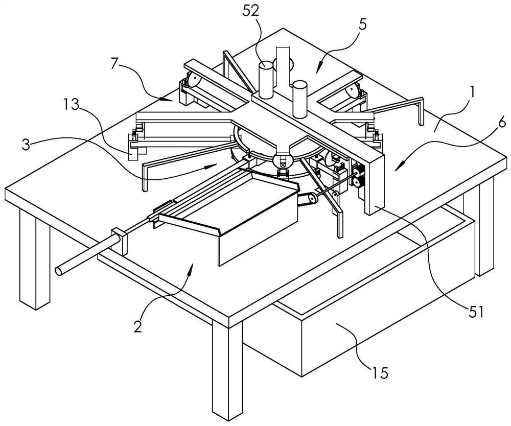
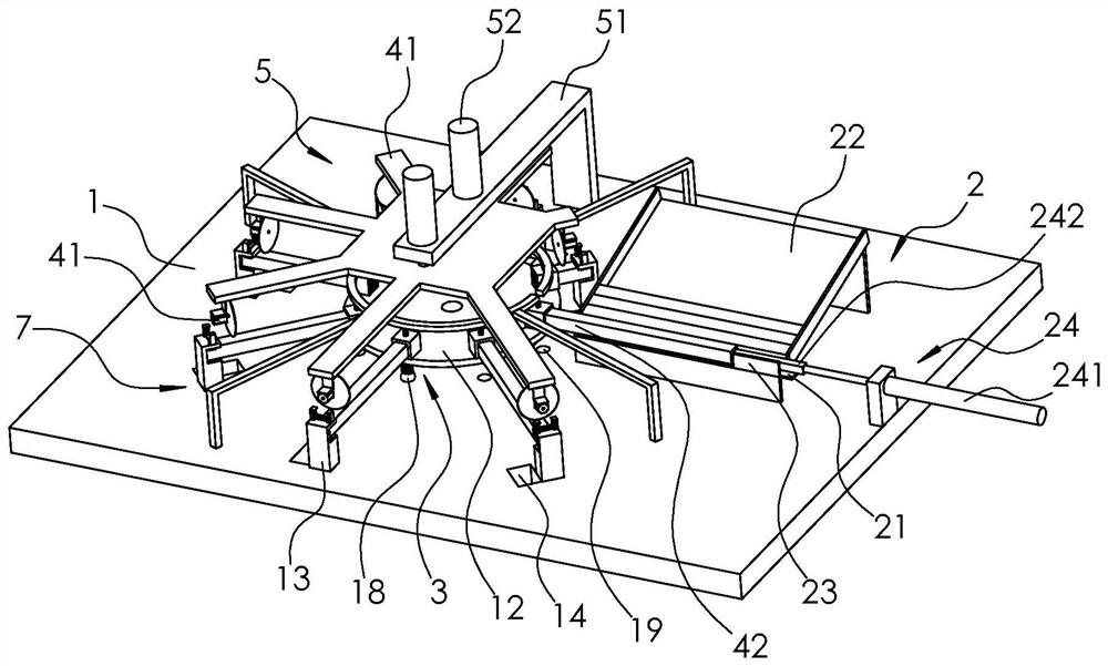
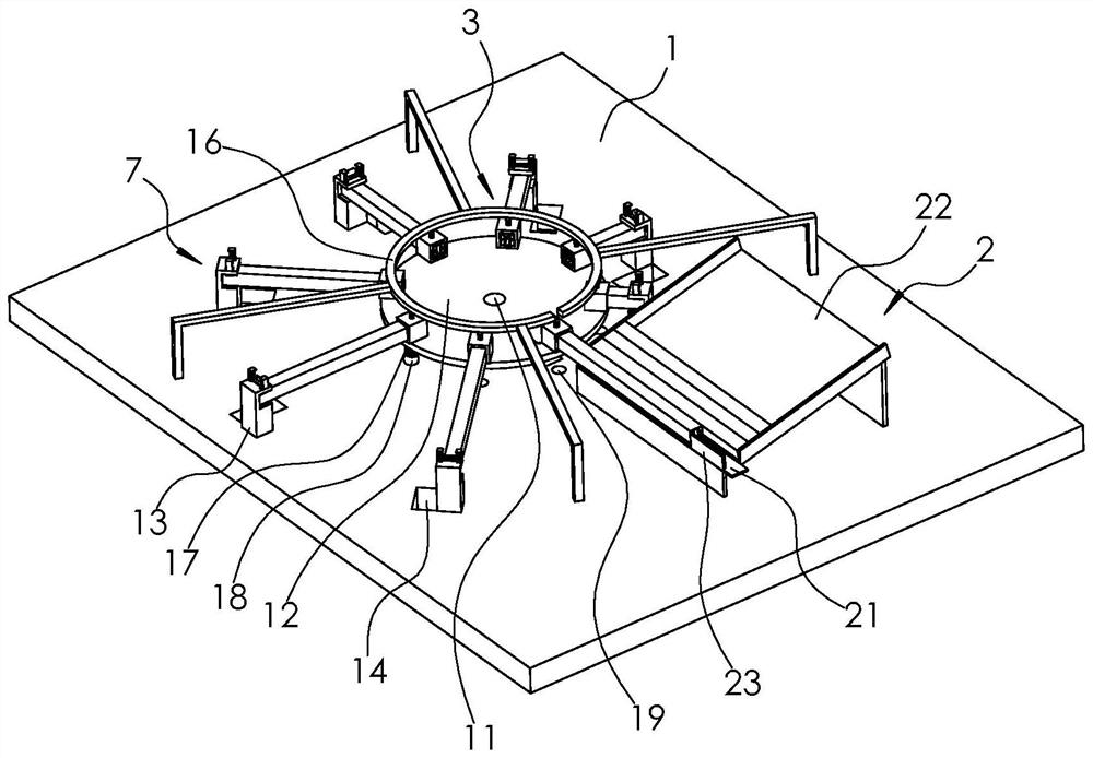
[0044] The embodiment of the present application discloses a profile cutting device. like figure 1 , figure 2 and image 3 As shown, a profile cutting device includes a workbench 1 and a feeding mechanism 2. A turntable 12 is rotatably connected to the workbench 1 through a vertical shaft 11. The turntable 12 is provided with several clamps 3 arranged in a circumferential direction. The feeding mechanism 2 is used to feed the profile to the fixture 3, and the fixture 3 is used to clamp and fix the profile; above the workbench 1 is provided with a mounting plate 4 and a lifting mechanism 5, and on the mounting plate 4 are installed a number of wheels that surround the outer side of the turntable 12 The cutting machine 41 and the lifting mechanism 5 are used to drive the mounting plate 4 up and down, so that multiple sets of cutting machines 41 jointly cut the profiles on the fixt...


PUM


Abstract

The invention relates to the technical field of metal cutting, and particularly relates to a section bar cutting device. The section bar cutting device comprises a workbench, wherein a rotary disc is rotatably connected on the workbench; a plurality of clamps which are arranged in the peripheral direction are arranged on the rotary disc; a mounting plate and a lifting mechanism for driving the mounting plate to lift are arranged above the workbench; a plurality of cutting machines which surround the outer side of the rotary disc are mounted on the mounting plate; a replacing region is arranged between every two adjacent groups of cutting machines; an included angle formed by a connecting line between the two groups of cutting machines and the center of the rotary disc is twice of an included angle formed by a connecting line between every two adjacent groups of cutting machines and the center of the rotary disc; horizontal distances between each group of cutting machines and the center of the rotary disc are different; a plurality of dropping slots are formed in the workbench; and the rotary disc drives section bars to push workpieces into the dropping slots through the clamps. The section bar cutting device can improve cutting efficiency of the section bars.

Description

technical field [0001] The present application relates to the technical field of metal cutting, in particular to a profile cutting device. Background technique [0002] Profile refers to a solid straight bar with a certain cross-sectional shape and size after plastic processing. Profiles are objects with a certain geometric shape made of iron or steel and materials with certain strength and toughness through rolling, extrusion, casting and other processes. This type of material has a certain appearance size, a certain cross-section shape, and certain mechanical and physical properties. Profiles can be used alone or further processed into other manufactured products, often used in building structures and manufacturing installations. Mechanical engineers can select the specific shape, material, heat treatment state, mechanical properties and other parameters of the profile according to the design requirements, and then divide the profile according to the specific size and sh...

Claims


Application Information

Patent Timeline
Patent Type & Authority Applications(China)
IPC IPC(8): B23D47/04B23D45/10B23Q7/02B23Q7/06
CPCB23D47/04B23D45/10B23Q7/02B23Q7/06
Inventor 不公告发明人
Owner 郭景兵
Learn More