Integrated circuit board welding foot cutting device

A technology for integrated circuit boards and cutting devices, which is applied in the direction of welding/welding/cutting items, auxiliary devices, welding equipment, etc. It can solve problems that affect the use of circuit boards, affect cutting quality, and loose solder feet, so as to improve quality and effect , Good supporting effect, avoiding the effect of welding leg bending

Active Publication Date: 2021-10-22
TIANJIN UNIV
View PDF10 Cites 4 Cited by
  • Summary
  • Abstract
  • Description
  • Claims
  • Application Information

AI Technical Summary

Problems solved by technology

[0002] With the continuous development of the electronic information manufacturing industry, the demand for circuit boards is gradually increasing. After the circuit board is manufactured, different components need to be welded on the circuit board. In the prior art, the cutting of the welding feet of the circuit board is often carried out directly by using a high-speed rotating cutter head. When cutting, the welding feet will be applied with a thrust parallel to the movement of the circuit board or the direction of the cutter head. And the tangential force in the rotation direction of the cutter head, when the cutting feed rate is too large or the sharpness of the cutter head decreases, it will cause the solder leg to bend. After the solder leg bends, it will first affect the cutting quality, and secondly affect the use of the circuit board. It even leads to the loosening of the welding feet, which brings many unnecessary troubles; the cutting of the welding feet and the grinding of the cutting position are generally two steps, and it is impossible to perform simultaneous cutting and grinding, which is inconvenient

Method used


Image

  • Integrated circuit board welding foot cutting device
  • Integrated circuit board welding foot cutting device
  • Integrated circuit board welding foot cutting device

Examples


Embodiment Construction

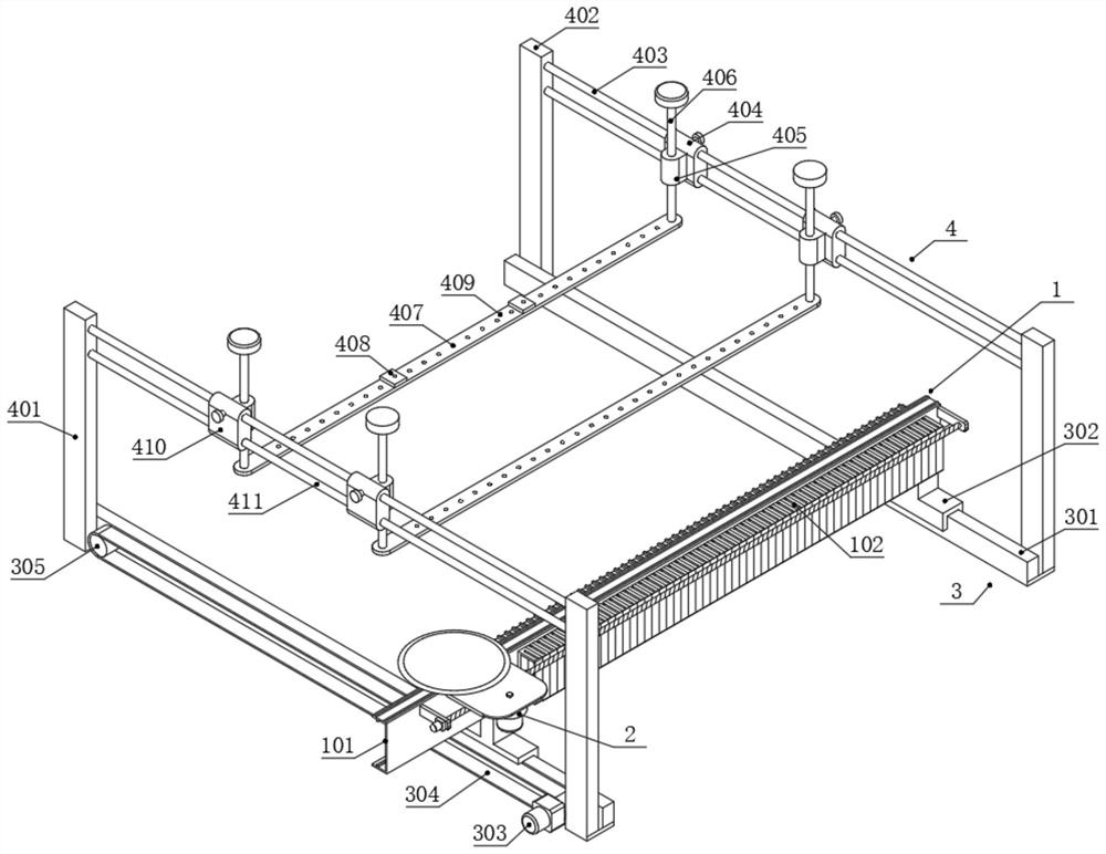
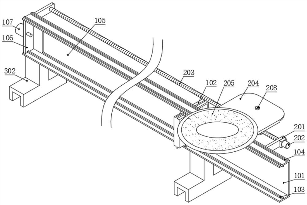
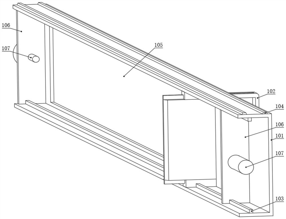
[0028] see figure 1 , an integrated circuit board welding leg cutting device, including a welding leg clamping mechanism 1, a mobile cutting mechanism 2, a support mechanism 3 and a fixing mechanism 4, and the welding leg clamping mechanism 1 is slidably connected to the top of the support mechanism 3, so The mobile cutting mechanism 2 is arranged on the top of the welding leg clamping mechanism 1 along the length direction of the welding leg clamping mechanism 1, the fixing mechanism 4 is arranged above the supporting mechanism 3, and the welding leg clamping The holding mechanism 1 and the moving cutting mechanism 2 are located between the supporting mechanism 3 and the fixing mechanism 4; the solder leg clamping mechanism 1 clamps the solder leg 5 of the circuit board.

[0029] The support mechanism 3 includes two or more guide rails 301 parallel to each other and a linear slide 302 movably connected to the guide rails 301. One side and two ends of the guide rails 301 are r...


PUM


Abstract

The invention discloses an integrated circuit board welding foot cutting device. The integrated circuit board welding foot cutting device comprises a welding foot clamping mechanism, a movable cutting mechanism, a supporting mechanism and a fixing mechanism, wherein the welding foot clamping mechanism is connected to the top of the supporting mechanism in a sliding mode, the movable cutting mechanism is arranged at the top of the welding foot clamping mechanism in the length direction of the welding foot clamping mechanism, and the fixing mechanism is arranged above the supporting mechanism. According to the integrated circuit board welding foot cutting device, the welding foot clamping mechanism is arranged so that welding feet located in the same row can be clamped and fixed one by one, then the welding feet can be prevented from being bent during cutting, and the cutting quality and effect are improved; a clamping assembly can synchronously clamp the plurality of welding feet at different positions in the same row or an approximate row, and the cutting of circuit boards at different welding foot positions is met; and the two sides of the end part of a telescopic plate are inclined surfaces, so that the telescopic plate can be better attached to the side walls of the welding feet, and a good supporting effect is achieved.

Description

technical field [0001] The invention relates to the technical field of circuit board welding leg cutting. Specifically, the utility model relates to a cutting device for solder feet of an integrated circuit board. Background technique [0002] With the continuous development of the electronic information manufacturing industry, the demand for circuit boards is gradually increasing. After the circuit board is manufactured, different components need to be welded on the circuit board. In the prior art, the cutting of the welding feet of the circuit board is often carried out directly by using a high-speed rotating cutter head. When cutting, the welding feet will be applied with a thrust parallel to the movement of the circuit board or the direction of the cutter head. And the tangential force in the rotation direction of the cutter head, when the cutting feed rate is too large or the sharpness of the cutter head decreases, it will cause the solder leg to bend. After the solder...

Claims


Application Information

Patent Timeline
Patent Type & Authority Applications(China)
IPC IPC(8): B23K3/00B23K3/08B23K101/36
CPCB23K3/00B23K3/087B23K2101/36
Inventor 崔洋梁继然
Owner TIANJIN UNIV
Why Eureka
Try Eureka