Welding tool clamp for manufacturing grid type guardrails

A technology for welding fixtures and guardrails, which is applied in the direction of manufacturing tools, welding equipment, welding equipment, etc., can solve the problems that affect the quality of guardrail finished products during the welding process of guardrails, and the horizontal bars and grid bars are prone to shaking, so as to ensure accurate alignment , to avoid the effect of shaking

Active Publication Date: 2021-10-22
烟台佑利技术有限公司
View PDF8 Cites 10 Cited by
  • Summary
  • Abstract
  • Description
  • Claims
  • Application Information

AI Technical Summary

Problems solved by technology

[0002] The schematic diagram of the grid-type guardrail structure completed by welding is as follows Figure 8 As shown, the existing grid-type guardrail is mainly manufactured and processed by welding, and the following problems still exist in the welding process of the existing grid-type guardrail: a. The grid bars used in the existing grid-type guardrail There are many types and shapes and sizes. The grid bars mainly include round tubes, square tubes, and strip steel plates. However, most of the existing welding fixtures for grid guardrails can only be welded for one specification of guardrails. ; b. The existing guardrails will adjust the spacing between adjacent grid bars according to the actual situation during the welding process, and most of the existing fixtures do not have a spacing adjustment function, and can only be used for grid bars with one spacing Welding is carried out, and at the same time, the horizontal bars and grille bars are prone to shake when the existing fixtures are welding the guardrail, which affects the welding process of the guardrail and the quality of the finished product of the guardrail

Method used


Image

  • Welding tool clamp for manufacturing grid type guardrails
  • Welding tool clamp for manufacturing grid type guardrails
  • Welding tool clamp for manufacturing grid type guardrails

Examples


Embodiment Construction

[0027] Embodiments of the present invention will be described below with reference to the accompanying drawings; during this process, in order to ensure the clarity and convenience of the description, we may exaggerate the width of the lines or the size of the constituent elements in the illustrations.

[0028] In addition, the following terms are defined based on the functions in the present invention, and may be different according to user's intention or practice. Therefore, these terms are defined based on the entire content of this specification.

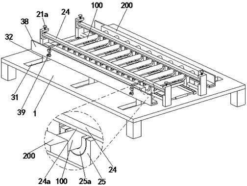
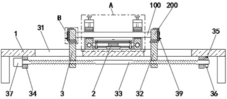
[0029] refer to figure 1 and figure 2 , a grid-type guardrail manufacturing welding fixture, including a workbench 1, a clamping mechanism 2 and an alignment mechanism 3, the workbench 1 is provided with a clamping mechanism 2 and an alignment mechanism 3, and the alignment The mechanism 3 is located on both sides of the clamping mechanism 2 .

[0030] refer to Figure 1 to Figure 6 , the clamping mechanism 2 includes a fi...


PUM


Abstract

The invention relates to the technical field of guardrail welding and manufacturing, in particular to a welding tool clamp for manufacturing grid type guardrails. The welding tool clamp comprises a workbench, a clamping mechanism and alignment mechanisms, wherein the clamping mechanism and the alignment mechanisms are arranged on the workbench, and the alignment mechanisms are located on the two sides of the clamping mechanism. According to the welding tool clamp, a function of welding and manufacturing the grid type guardrails in different shapes can be fulfilled, meanwhile, the distance between every two adjacent grid bars can be adjusted, so that the grid type guardrails with different specifications can be welded and manufactured; and the grid bars with different lengths can be welded and manufactured, so that the guardrails with different specifications and heights can be manufactured.

Description

technical field [0001] The invention relates to the technical field of guardrail welding production, in particular to a grid-type guardrail production welding fixture. Background technique [0002] The schematic diagram of the grid-type guardrail structure completed by welding is as follows Figure 8 As shown, the existing grid-type guardrail is mainly manufactured and processed by welding, and the following problems still exist in the welding process of the existing grid-type guardrail: a. The grid bars used in the existing grid-type guardrail There are many types and shapes and sizes. The grid bars mainly include round tubes, square tubes, and strip steel plates. However, most of the existing welding fixtures for grid guardrails can only be welded for one specification of guardrails. ; b. The existing guardrails will adjust the spacing between adjacent grid bars according to the actual situation during the welding process, and most of the existing fixtures do not have a sp...

Claims


Application Information

Patent Timeline
Patent Type & Authority Applications(China)
IPC IPC(8): B23K37/04B23K31/02
CPCB23K37/0426B23K31/02
Inventor 王磊
Owner 烟台佑利技术有限公司
Why Eureka
Try Eureka