
A glass cutting and feeding system

A glass cutting and glass technology, which is applied in the field of glass cutting and feeding system, can solve the problems of broken glass plate and transmission wheel, glass broken, difficult to control, etc., and achieve the effect of desorption, avoiding fragmentation and avoiding collision

Active Publication Date: 2021-12-07
JIANGSU JIAYI BEIKE OPTICS TECH CO LTD
View PDF1 Cites 0 Cited by
  • Summary
  • Abstract
  • Description
  • Claims
  • Application Information

AI Technical Summary

Problems solved by technology

[0005] When the glass plate used for feeding is thin, after the "turning arm reaches the horizontal direction, at this time, the glass is slightly higher than the upper edge of the transmission wheel, at this time, the vacuum suction cup stops working, loosen the glass, and the lifting cylinder When retracting, the entire turning mechanism moves downward relative to the trolley. During the falling process, the glass falls on the transmission wheel, and the upper edge of the vacuum suction cup is slightly lower than the glass. During the process, the glass will fall down for a certain distance, and the thinner glass The point contact and collision between the suction cup and the transmission wheel can easily cause glass fragmentation; and if the direct control of the turning mechanism drives the glass plate to contact with the transmission wheel, it is difficult to accurately control the separation time point between the suction cup and the glass plate, resulting in glass Fragmentation caused by excessive compression between the plate and the transfer wheel

Method used


Image

  • A glass cutting and feeding system
  • A glass cutting and feeding system

Examples


Embodiment Construction

[0023] The present invention will be described in further detail below in conjunction with the accompanying drawings.

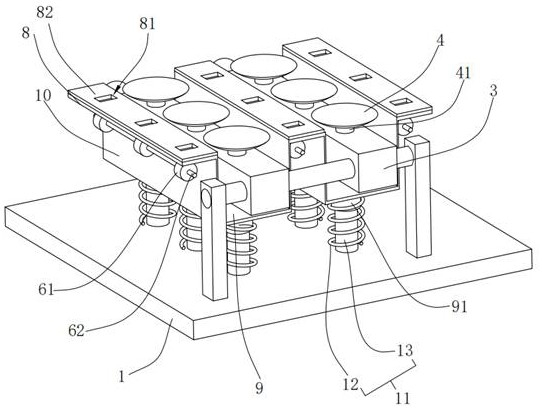
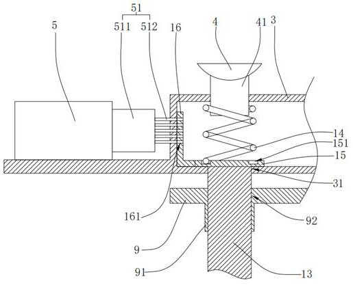
[0024] Such as figure 1 and figure 2 As shown, a glass cutting and feeding system includes a trolley 1, a glass turning mechanism and a glass transmission mechanism, wherein the structure of the trolley 1, the rotating structure in the glass turning mechanism and the glass transmission mechanism can all adopt the same structure as the prior art , so it will not be repeated in this embodiment.

[0025] Also installed on the trolley 1 is an elevating support mechanism for buffering the impact force when the glass is in contact with the transmission wheel 61. The elevating support mechanism includes a support plate 8 above the transmission shaft 62, an elevating plate 9 between the transmission shafts 62 and a supporting lifting mechanism. The elastic support assembly 11 of the plate 9, wherein the upper end of the support plate 8 is pasted with a layer of sp...


PUM


Abstract

The present invention relates to the technical field of glass processing, and discloses a glass cutting and feeding system, which includes a trolley 1, a glass turning mechanism and a glass transmission mechanism, and the trolley 1 is also equipped with a device for buffering the impact force when the glass contacts the transmission wheel 61. Lifting support mechanism, the lifting support mechanism includes a support plate 8 located above the transmission shaft 62, a lift plate 9 located between the phase transmission shafts 62, and an elastic support assembly 11 supporting the lift plate 9, wherein the upper end of the support plate 8 is pasted with a layer Sponge pad 82, fixed plate 10 is installed between lifting plate 9 and adjacent support plate 8, fixed plate 10 is vertically arranged, and support plate 8, fixed plate 10 and lifting plate 9 form an integral structure, simultaneously on support plate 8 is provided with an avoidance groove 81, and the avoidance groove 81 runs through the support plate 8 along the vertical direction; the cooperation between the lifting support structure and the glass turning mechanism makes the glass transfer to the transmission wheel smoothly, ensuring the safety of feeding.

Description

technical field [0001] The invention relates to the technical field of glass processing, in particular to a glass cutting and feeding system. Background technique [0002] Glass processing includes many steps, the first step is the raw material loading process, which is mainly to move the glass to be processed to the horizontal processing platform, and then cut the glass and other processing. [0003] The patent with the existing notification number CN206512095U discloses a new type of glass automatic feeding device, including a trolley, a glass turning mechanism, a glass transmission mechanism and a driving device. The glass turning mechanism includes a turning arm, a turning link, a crank, a turning drive device, fixed arm, lifting cylinder and vacuum cups. [0004] When feeding, the glass is placed upright on the glass stacking rack at a specific angle of inclination to prevent the glass from falling. When the work starts, the trolley moves linearly to the right along t...

Claims


Application Information

Patent Timeline
Patent Type & Authority Patents(China)
IPC IPC(8): B65G49/06
CPCB65G49/061
Inventor 张耀孟威
Owner JIANGSU JIAYI BEIKE OPTICS TECH CO LTD
Learn More