
Ammonia synthesis tower for cascade recovery of waste heat and renewable energy source ammonia synthesis system

A ammonia synthesis tower and cascaded recovery technology, which is applied in energy input, ammonia compounds, climate sustainability, etc., can solve the problems that the reaction temperature does not match the optimum temperature, the reactor temperature is uneven, and the equipment process is complex, etc., to achieve high efficiency Effects of heat transfer, high energy efficiency, and simplified process flow

Active Publication Date: 2021-10-22
FUZHOU UNIV ASSET MANAGEMENT CO LTD
View PDF9 Cites 0 Cited by
  • Summary
  • Abstract
  • Description
  • Claims
  • Application Information

AI Technical Summary

Problems solved by technology

[0007] The present invention aims to solve the problems that the reaction process of ammonia synthesis and the heat recovery process are relatively independent in the traditional process, resulting in complex equipment and multiple processes, as well as the uneven temperature of the reactor and the mismatch between the reaction temperature and the optimum temperature, so as to provide a new type of high-efficiency and compact Waste heat cascade recovery ammonia synthesis tower and renewable energy ammonia synthesis system

Method used


Image

  • Ammonia synthesis tower for cascade recovery of waste heat and renewable energy source ammonia synthesis system
  • Ammonia synthesis tower for cascade recovery of waste heat and renewable energy source ammonia synthesis system
  • Ammonia synthesis tower for cascade recovery of waste heat and renewable energy source ammonia synthesis system

Examples


Embodiment 1

[0059] Ammonia tower level:

[0060] The volume ratio of hydrogen to nitrogen at the inlet of the raw material gas into the pipe is 2.5:1, the pressure is 10MPa, and the temperature is 25°C;

[0061] Ammonia synthesis catalyst bed, the space velocity is 5000h -1 ;

[0062] The catalyst bed outlet temperature is 400°C;

[0063] The inlet pressure of the high-pressure water in the water inlet pipe is 16.5MPa, and the temperature is 25°C;

[0064] The temperature of the high-pressure steam at the outlet of the steam pipeline is 350°C and the pressure is 16.5MPa;

[0065] The medium-pressure steam at the outlet of the steam pipeline has a temperature of 320°C and a pressure of 11MPa;

[0066] The ammonia concentration at the outlet of the product gas outlet pipe is 21.5%.

[0067] System technology level:

[0068] In the grid-connected mode, the renewable energy is connected to the grid within the capacity allowed by the grid, and the excess power is used to electrolyze wate...

Embodiment 2

[0075] Ammonia tower level:

[0076] The volume ratio of hydrogen to nitrogen at the inlet of the raw material gas into the pipe is 2.5:1, the pressure is 7MPa, and the temperature is 25°C;

[0077] Ammonia synthesis catalyst bed, the space velocity is 5000h -1 ;

[0078] The catalyst bed outlet temperature is 400°C;

[0079] The inlet pressure of the high-pressure water in the water inlet pipe is 16.5MPa, and the temperature is 25°C;

[0080] The temperature of the high-pressure steam at the outlet of the steam pipeline is 350°C and the pressure is 16.5MPa;

[0081] The medium-pressure steam at the outlet of the steam pipeline has a temperature of 320°C and a pressure of 11MPa;

[0082] The ammonia concentration at the outlet of the product gas outlet pipe is 16.8%.

[0083] System technology level:

[0084] The working pressure of the electrolyzed water device is 7.5MPa, and the working temperature is 80°C;

[0085] The hydrogen-nitrogen volume ratio of raw material g...

Embodiment 3

[0091] Ammonia tower level:

[0092] The volume ratio of hydrogen to nitrogen at the inlet of the raw material gas into the pipe is 2.5:1, the pressure is 10MPa, and the temperature is 25°C;

[0093] Ammonia synthesis catalyst bed, the space velocity is 5000h -1 ;

[0094] The catalyst bed outlet temperature is 400°C;

[0095] The inlet pressure of the high-pressure water in the water inlet pipe is 14MPa, and the temperature is 25°C;

[0096] The temperature of the high-pressure steam at the outlet of the steam pipeline is 360°C and the pressure is 14MPa;

[0097] The medium-pressure steam at the outlet of the steam pipeline has a temperature of 340°C and a pressure of 11MPa;

[0098] The temperature of the low-pressure steam at the outlet of the steam pipeline is 320°C and the pressure is 8MPa;

[0099] The ammonia concentration at the outlet of the product gas outlet pipe is 21.5%.

[0100] System technology level:

[0101] The working pressure of the electrolyzed wat...


PUM


Abstract

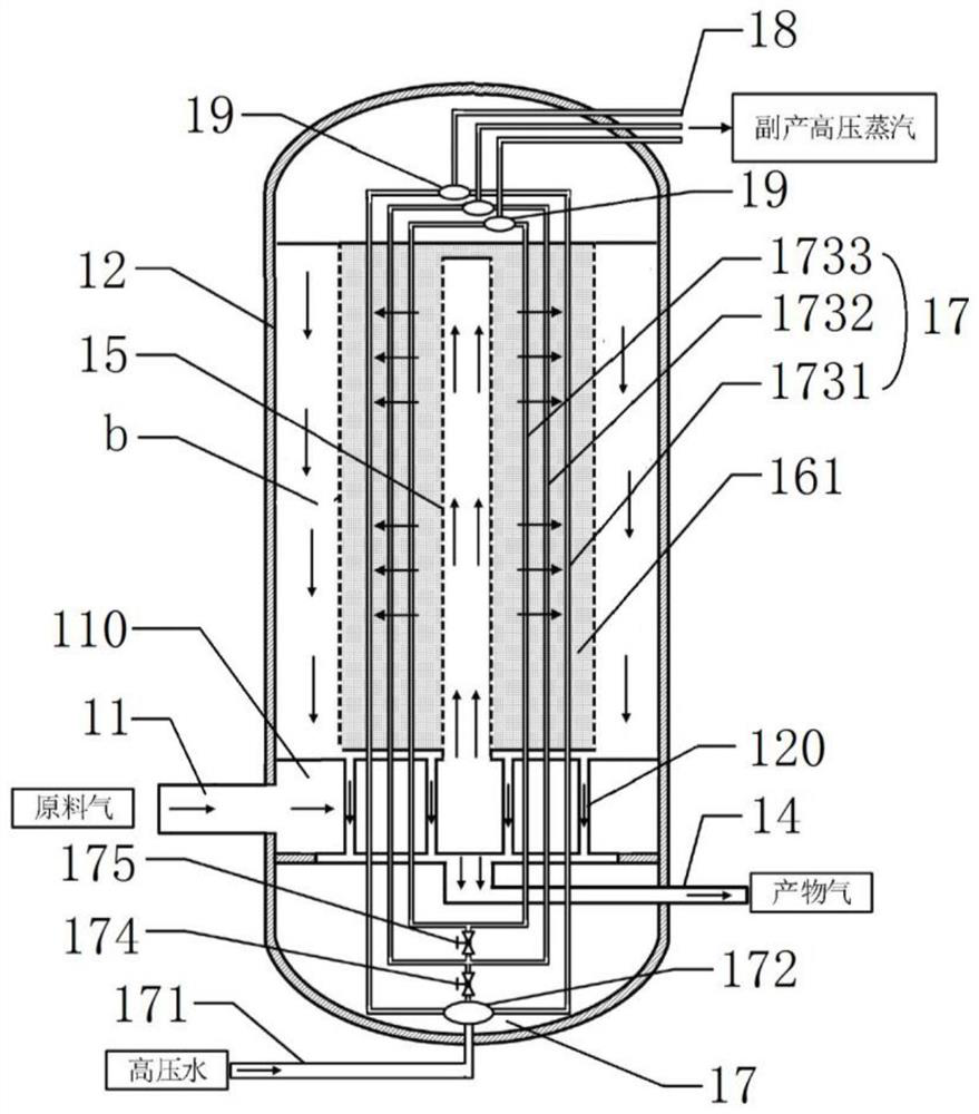
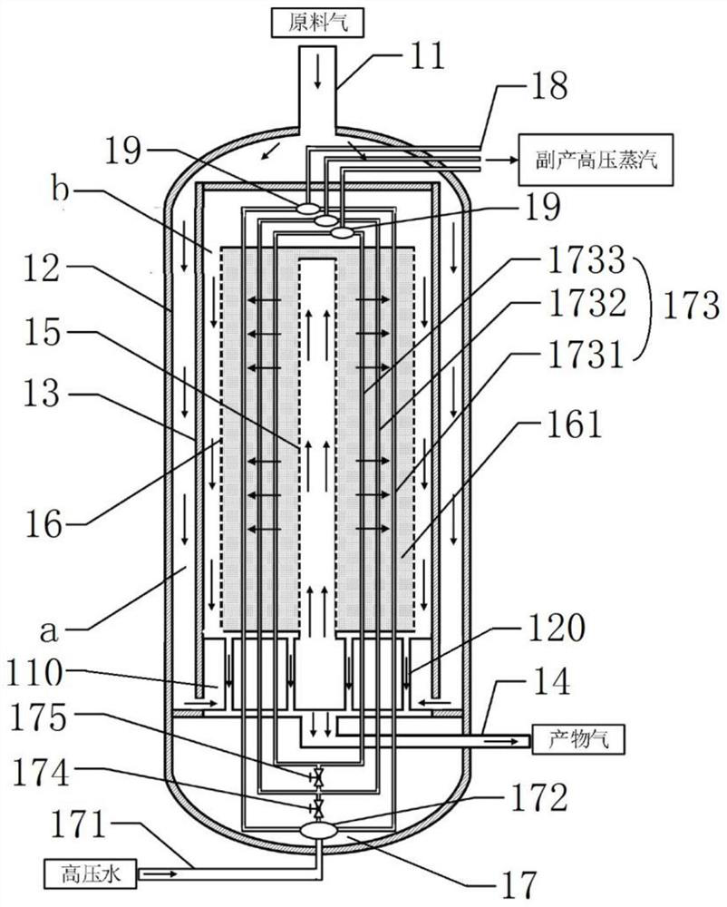
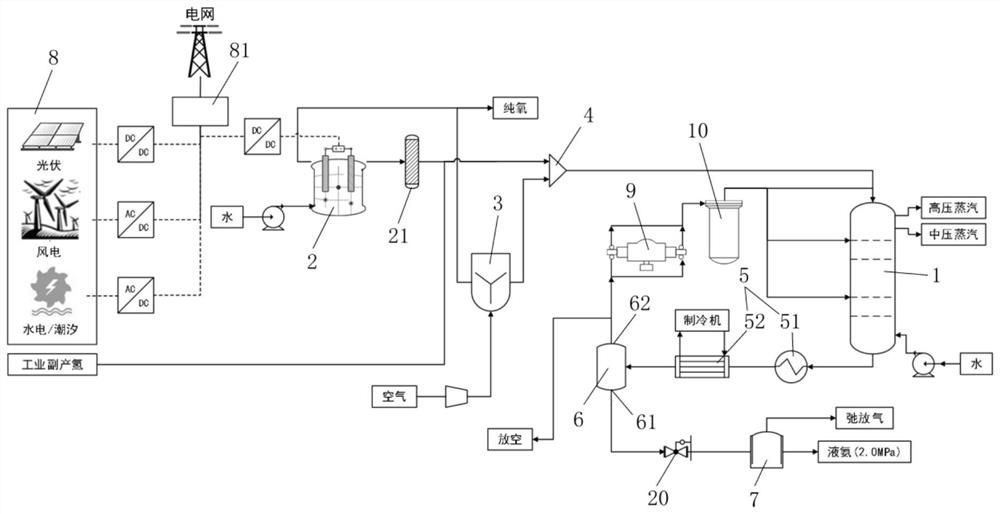
The invention discloses an ammonia synthesis tower for cascade recovery of waste heat, and a renewable energy source ammonia synthesis system. The ammonia synthesis tower comprises a reactor outer cylinder, a raw material gas inlet pipe and a product gas outlet pipe, wherein a catalyst bed is sleeved with the reactor outer cylinder, an annular gap channel II is formed between the reactor outer cylinder and the catalyst bed, one end is communicated with the product gas outlet pipe, a central pipe is arranged in the middle of the catalyst bed, one end of the central pipe is communicated with the raw material gas inlet pipe, the other end of the central pipe is sealed in the catalyst bed, a plurality of gas holes are formed in the pipe wall of the central pipe in the axial direction, a plurality of first heat exchange tube bundles penetrating through the interior of the catalyst bed are arranged at intervals in the axial direction of the catalyst bed, one end of each first heat exchange tube bundle is communicated with a water tube with different input water pressure, and the other end of each first heat exchange tube bundle is communicated with a steam tube set. The ammonia synthesis tower disclosed by the invention can be used for efficiently transferring heat, preheating raw material gas and by-produce steam with different temperature grades, achieves accurate temperature control on a bed layer by regulating and controlling the byproduct steam, facilitates ammonia synthesis reaction, and has the advantages of energy conservation and consumption reduction.

Description

technical field [0001] The invention relates to the technical field of clean energy conversion and storage, in particular to an ammonia synthesis tower with cascaded recovery of waste heat and a renewable energy synthesis ammonia system. Background technique [0002] At present, my country's wind energy, solar energy and other renewable energy power generation industries are developing rapidly, but these renewable energy sources fluctuate greatly due to the influence of seasons and weather conditions, and do not fully match the relatively stable electricity demand. In order to reduce the fluctuation of renewable energy Negative impacts on the power grid often lead to "abandonment of wind", "abandonment of light" and "abandonment of water" and other "three abandonment" phenomena, resulting in a low utilization rate of renewable energy. my country's annual "three waste" electricity scale is as high as 100 billion kWh, which is equivalent to the annual power generation of the Th...

Claims


Application Information

Patent Timeline
IPC IPC(8): C01C1/04C25B1/04C25B9/65
CPCC01C1/0417C01C1/0452C01C1/0411C25B1/04C25B9/65Y02P20/133
Inventor 罗宇江莉龙林立倪军陈崇启
Owner FUZHOU UNIV ASSET MANAGEMENT CO LTD
Learn More