
Gas chamber temperature fluctuation error suppression method for atomic gyroscope

A technology of temperature fluctuation and atomic gyroscope, which is applied to instruments, navigation through speed/acceleration measurement, and measurement devices, etc., can solve the problems of gyroscope sensitivity and long-term stability decline, gyroscope signal strength change, and increase system complexity. Achieve the effect of suppressing the influence of sensitivity and long-term stability, improving stability, and facilitating miniaturization

Active Publication Date: 2021-10-22
BEIHANG UNIV
View PDF7 Cites 0 Cited by
  • Summary
  • Abstract
  • Description
  • Claims
  • Application Information

AI Technical Summary

Problems solved by technology

The temperature of the gas chamber determines the atomic density of the alkali metal. The fluctuation of the atomic density will cause the change of the signal strength of the gyroscope, which will lead to the decrease of the sensitivity and long-term stability of the gyroscope.
At present, electric heating is used to heat the alkali metal gas chamber, and closed-loop control is used to reduce the fluctuation of the temperature of the gas chamber, but the room for improving the accuracy of the gas temperature control is limited, and further improving the accuracy of the gas temperature control circuit will greatly increase the system temperature. The complexity is not conducive to the application of gyro

Method used


Image

  • Gas chamber temperature fluctuation error suppression method for atomic gyroscope
  • Gas chamber temperature fluctuation error suppression method for atomic gyroscope
  • Gas chamber temperature fluctuation error suppression method for atomic gyroscope

Examples


Embodiment Construction

[0024] Below with the accompanying drawings ( Figure 1-Figure 3 ) and Examples illustrate the present invention.

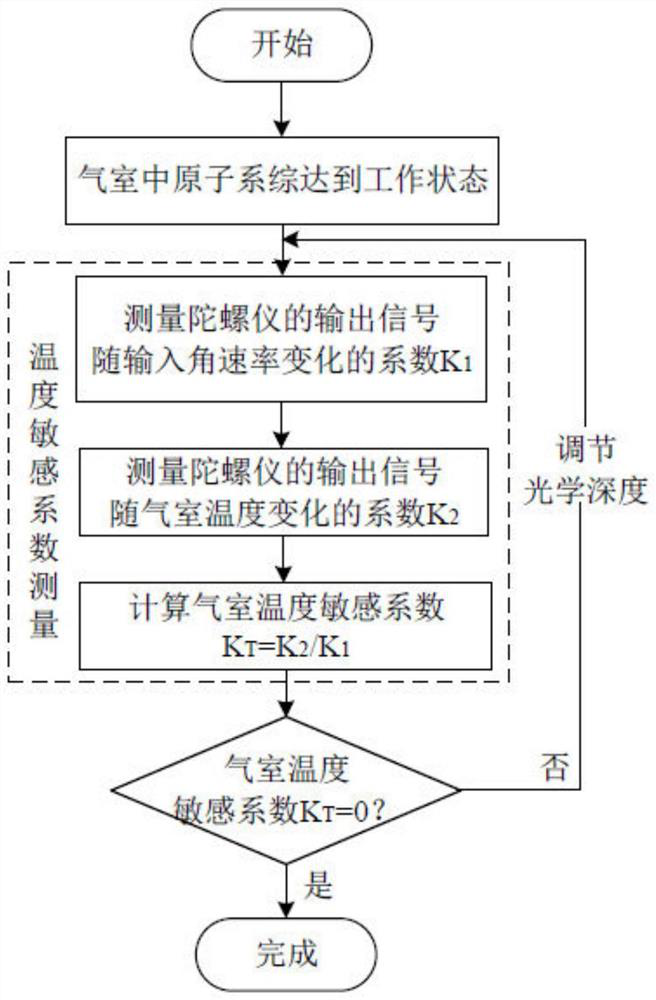
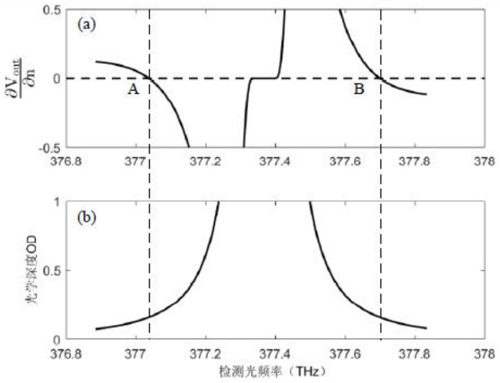
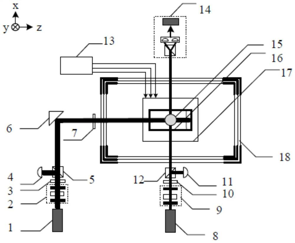
[0025] figure 1 It is a schematic flow chart of implementing an air chamber temperature fluctuation error suppression method of an atomic gyroscope of the present invention. figure 2 a is a schematic diagram of the relationship between the derivative of the gyroscope output signal and the atomic density as a function of the detection light frequency. figure 2 b is a schematic diagram of the relationship between the atomic optical depth and the detection light frequency. image 3 It is a schematic structural diagram of an experimental system for implementing an air chamber temperature fluctuation error suppression method for an atomic gyroscope of the present invention. refer to Figure 1 to Figure 3 As shown, a gas chamber temperature fluctuation error suppression method for an atomic gyroscope, the gas chamber filled with alkali metal atoms and inert gas i...


PUM


Abstract

The invention discloses a gas chamber temperature fluctuation error suppression method for an atomic gyroscope. The method comprises the following steps of: firstly, heating, pumping and performing magnetic field compensation on a gyroscope to enable the gyroscope to reach a working state; then calibrating a coefficient of an output signal of the gyroscope changing along with an input angular rate; calibrating a coefficient of an output signal of the gyroscope changing along with the temperature of a gas chamber, dividing the coefficient by the coefficient of the output signal changing along with the input angular rate, and calculating the temperature sensitivity coefficient of the gas chamber of the gyroscope; and finally, reducing the temperature sensitivity coefficient of the gas chamber of the gyroscope to zero by adjusting the optical depth of the alkali metal atoms to the detection light for multiple times, so as to enable the output signal of the gyroscope not to be sensitive to the fluctuation of the temperature of the gas chamber any more. Therefore, the angular rate measurement error of the gyroscope caused by the fluctuation of the temperature of the gas chamber is inhibited, and the stability of the gyroscope is improved. Meanwhile, the method reduces the requirement of the gyroscope on the precision of a gas chamber temperature control circuit, reduces the complexity of the system, and facilitates the miniaturization of the gyroscope.

Description

technical field [0001] The invention relates to an air chamber temperature fluctuation error suppression method of an atomic gyroscope, which provides necessary conditions for the use of a high-precision gyroscope and belongs to the field of atomic gyroscopes. Background technique [0002] High-precision inertial navigation is of great significance. The gyroscope is the sensitive core of the inertial navigation system and determines the overall performance of the inertial navigation system. In recent years, with the development of quantum science and technology, the atomic spin gyroscope based on the relaxation effect without spin exchange can sense the change of inertial angular rate with ultra-high sensitivity, which is one of the important development directions of the new generation of high-precision gyroscope. one. High temperature and low magnetic environment are the necessary conditions to realize the spin-exchange-free relaxation state of alkali metal atoms, and the...

Claims


Application Information

Patent Timeline
Patent Type & Authority Applications(China)
IPC IPC(8): G01C21/16G01C25/00
CPCG01C21/183G01C25/005Y02E30/10
Inventor 全伟刘佳丽姜丽伟梁逸翔
Owner BEIHANG UNIV
Learn More