

Long-wave infrared imaging optical system
An imaging optics and long-wave infrared technology, which is applied in the field of long-wave infrared imaging optical systems, can solve the problems of reduced imaging quality, blurred images, and decreased contrast of optical systems, and achieves easy follow-up processing and adjustment, reduced overall weight, and improved system structure. simple effect
- Summary
- Abstract
- Description
- Claims
- Application Information
AI Technical Summary
Problems solved by technology
Method used
Image

Examples
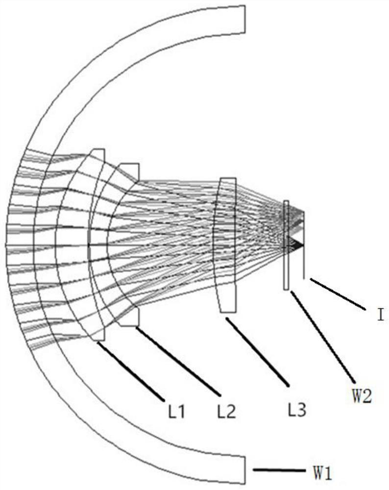
Embodiment 1
[0046] The parameters (radius, thickness, material, conic coefficient etc.) of each optical element among the present invention are as shown in table 1, and in the table, R is the radius of curvature of the optical surface, t is the distance with the latter optical surface, and D is the optical surface caliber, k is the conic coefficient of the optical surface, α 2 、α 3 、α 4 They are the coefficients of the fourth power, sixth power, and eighth power of the radial coordinates of the optical surface, respectively.
[0047] Table 1
[0048]
[0049] NOTE: Rotationally symmetric polynomial aspheres are described by polynomial expansions of deviation spheres (or aspheres defined by conic coefficients). The even-order asphere model describes the asphere in terms of even powers of radial coordinates only. This model uses the basic radius of curvature and conic factor. The surface coordinates are given by:
[0050]
[0051] Above-mentioned embodiment 1 can reach following...
Embodiment 2
[0061] The parameters (radius, thickness, material, conic coefficient, etc.) of each optical element in Example 2 of the present invention are shown in Table 2.
[0062] Table 2
[0063]
[0064]
[0065] Above-mentioned embodiment 2 can reach following index:
[0066] a) Focal length: 28.04mm;
[0067] b) F / #: 1;
[0068] c) Band: 8 ~ 14um;
[0069] d) Field of view: ±8°×±6°;
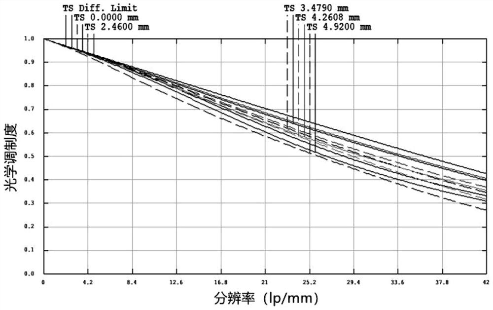
[0070] e) MTF: 0.42@42lp / mm, on-axis field of view;
[0071] f) Distortion: <|1|%;
[0072] g) Relative illuminance: >91%;
[0073] h) Ambient temperature: -40℃~60℃
Embodiment 3
[0075] The parameters (radius, thickness, material, conic coefficient, etc.) of each optical element in Example 3 of the present invention are shown in Table 3.
[0076] table 3
[0077]
[0078]
[0079] Above-mentioned embodiment 3 can reach following index:
[0080] a) Focal length: 27.93mm;
[0081] b) F / #: 1;
[0082] c) Band: 8 ~ 14um;
[0083] d) Field of view: ±8°×±6°;
[0084] e) MTF: 0.43@42lp / mm, on-axis field of view;
[0085] f) Distortion: <|1|%;
[0086] g) Relative illuminance: >94%;
[0087] h) Ambient temperature: -40℃~60℃
PUM
| Property | Measurement | Unit |
|---|---|---|
| Radius of curvature | aaaaa | aaaaa |
| Thickness | aaaaa | aaaaa |
| Thickness | aaaaa | aaaaa |
Abstract
Description
Claims
Application Information