Antenna structure, terminal and processing method of terminal

An antenna structure and terminal technology, which is applied to the connection of the antenna grounding switch structure, the antenna, the resonant antenna, etc., can solve the problems of poor performance and poor isolation of the antenna unit.

Active Publication Date: 2021-10-22
CHONGQING TRANSSION COMM TECH LTD
View PDF13 Cites 1 Cited by
  • Summary
  • Abstract
  • Description
  • Claims
  • Application Information

AI Technical Summary

Problems solved by technology

[0005] In view of the above problems, the embodiment of the present application provides an antenna structure, a te...

Method used


Image

  • Antenna structure, terminal and processing method of terminal
  • Antenna structure, terminal and processing method of terminal
  • Antenna structure, terminal and processing method of terminal

Examples


Embodiment 1

[0080] An embodiment of the present application provides an antenna structure, which can be set on a terminal, for example, on an electronic device such as a mobile phone or a tablet computer. The antenna structure of the embodiment of the present application can be one of the printed (Printed Antennas) antenna, LDS (Laser-Direct-structuring) antenna, steel antenna, and ceramic antenna. The structure is explained.

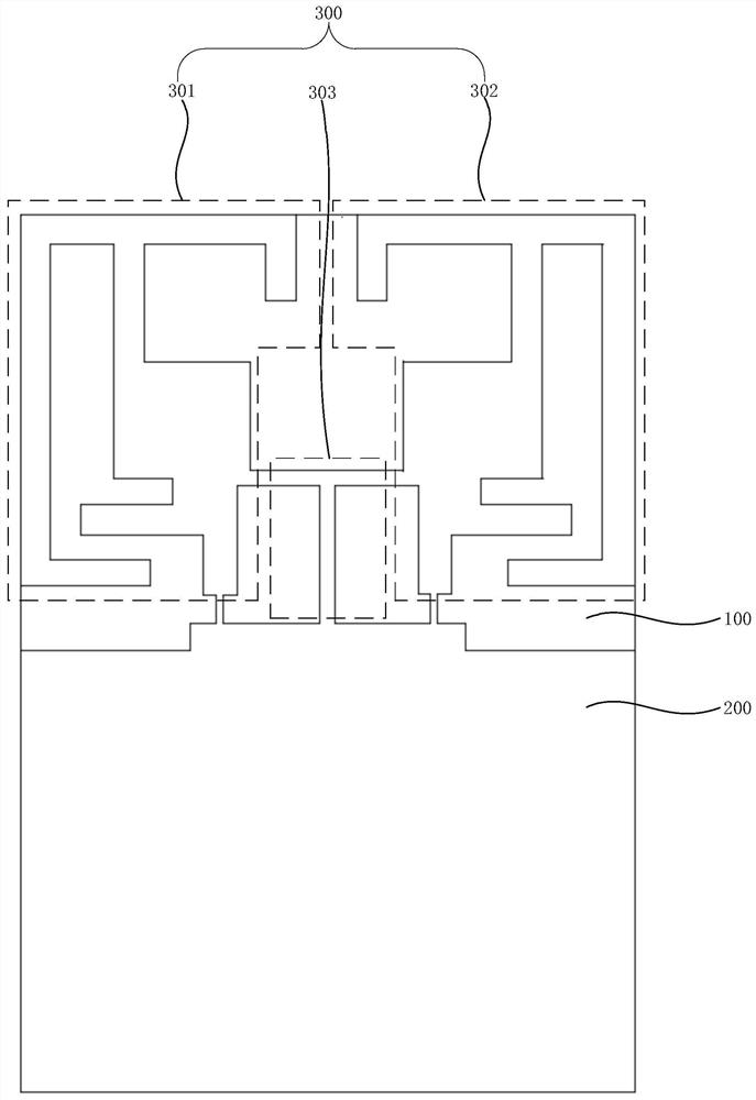
[0081] Please refer to figure 1 As shown, the antenna structure of the embodiment of the present application, which includes the antenna pattern area 300, is figure 1 In the illustrated embodiment, the length and width of the space occupied by the antenna pattern area 300 can be, for example, 0.16λ*0.11λ, optionally, λ=c / f, λ is the working wavelength of the antenna structure, c is the speed of light, f is the operating frequency of the antenna structure.

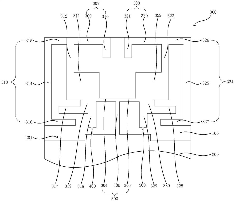
[0082] Please continue to refer to figure 1 As shown, the antenna pattern area 300 includes a first anten...

Embodiment 2

[0120] The embodiment of the present application further provides a terminal, which adopts the antenna structure of the embodiment of the present application, specifically, for example, electronic devices such as smart phones and tablet computers.

[0121] Please refer to Figure 9 , the terminal of the embodiment of the present application, which includes a transceiver 600, a first radio frequency transmission line 700, a second radio frequency transmission line 800, and the antenna structure 900 of the embodiment of the present application. The transceiver 600 is connected to the first antenna unit 301 through the first radio frequency transmission line 700 , and the transceiver 600 is connected to the second antenna unit 302 through the second radio frequency transmission line 800 . Optionally, the first radio frequency transmission line 700 is one of radio frequency coaxial lines, microstrip lines and strip lines, and the second radio frequency transmission line 800 is one...

Embodiment 3

[0131] The embodiment of the present application also provides a terminal processing method. Optionally, the terminal is the terminal in Embodiment 2, and the terminal processing method includes:

[0132] performing data processing on the source signal, and determining or generating a first transmitted signal and a second transmitted signal;

[0133] When transmitting, the first transmission signal is transmitted through the first antenna unit 301, and the second transmission signal is transmitted through the second antenna unit 302;

[0134] In receiving time sharing, the first received signal is received by the first antenna unit 301, and the second received signal is received by the second antenna unit 302;

[0135] Perform data processing on the first received signal and the second received signal, and determine or generate a sink signal.

[0136] In the terminal processing method of the embodiment of the present application, there is no sequence among the steps, and it c...


PUM


Abstract

The invention provides an antenna structure, a terminal and a processing method of the terminal. The antenna structure comprises a first antenna unit and a second antenna unit, and the tail end of a first coupling line of the first antenna unit and the tail end of a second coupling line of the second antenna unit are close to each other and are coupled. The terminal comprises the antenna structure, a transceiver, a first radio frequency transmission line and a second radio frequency transmission line, and the transceiver is connected with the first antenna unit through the first radio frequency transmission line and connected with the second antenna unit through the second radio frequency transmission line. The processing method of the terminal comprises the following steps: transmitting a first transmitting signal or receiving a first receiving signal through a first antenna unit, and transmitting a second transmitting signal or receiving a second receiving signal through a second antenna unit. According to the antenna structure, the terminal and the processing method of the terminal, the isolation degree between the antenna units is improved.

Description

technical field [0001] The present application relates to the technical field of antennas, and in particular to an antenna structure, a terminal and a terminal processing method. Background technique [0002] Multiple-Input Multiple-Output (MIMO, Multiple-Input Multiple-Output) technology is a technology that can significantly increase the data transmission rate and channel capacity without increasing the transmission power. The antenna structure used by the MIMO technology usually includes two More than one antenna unit to form more than two channels between the transceiver devices. [0003] During the process of conceiving and implementing the present application, the inventor found at least the following problems: when the multi-input multi-output antenna structure is arranged in the limited installation space of the terminal, the isolation between the antenna units becomes poor, resulting in poor performance. [0004] The foregoing description is provided to provide gen...

Claims


Application Information

Patent Timeline
IPC IPC(8): H01Q1/52H01Q1/50H01Q1/24H01Q1/22H01Q5/10H01Q5/30H01Q5/50H01Q9/04H04B1/38
CPCH01Q1/521H01Q1/243H01Q1/2266H01Q5/30H01Q5/10H01Q5/50H01Q1/50H01Q9/045H04B1/38
Inventor 王坤章富洪
Owner CHONGQING TRANSSION COMM TECH LTD
Why Eureka
Try Eureka