Brake power supply for construction hoist and control method

A technology for construction elevators and power supplies, which is applied in the direction of AC motor control, control systems, electrical components, etc., can solve the problems of construction elevators sliding down and down, and achieve the effects of enhancing safety, optimizing costs, and facilitating project realization and product installation

Active Publication Date: 2021-10-22
长沙市日业电气有限公司
View PDF10 Cites 0 Cited by
  • Summary
  • Abstract
  • Description
  • Claims
  • Application Information

AI Technical Summary

Problems solved by technology

The brake control of the construction elevator is particularly critical. If there is a problem with the brake at the end of the motor, such as insufficient braking torque, it will cause the construction elevator to slip

Method used


Image

  • Brake power supply for construction hoist and control method
  • Brake power supply for construction hoist and control method
  • Brake power supply for construction hoist and control method

Examples


Embodiment 1

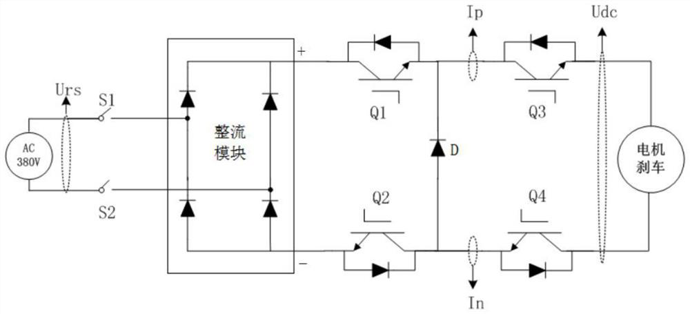
[0022] Example 1: See figure 1 , a brake power supply for a construction elevator, including a 380V power supply, a switch S1, a switch S2, a rectifier module, an IGBT switch Q1, an IGBT switch Q2, an IGBT switch Q3, an IGBT switch Q4, and a diode D, including a 380V power supply through the switch S1 and the switch S2 Connect the input terminal of the rectifier module, the output terminal of the rectifier module + the drain of the IGBT switch Q1, the source of the IGBT switch Q1 is connected to the cathode of the diode D and the drain of the IGBT switch Q3, and the source of the IGBT switch Q3 is connected to the motor brake module , the output terminal of the rectifier module-connect to the source of IGBT switch Q2, the drain of IGBT switch Q2 is connected to the anode of diode D and the source of IGBT switch Q4, the drain of IGBT switch Q4 is connected to the other end of the motor brake module, the IGBT switch The gates of Q1, IGBT switch Q2, IGBT switch Q3, and IGBT switc...

Embodiment 2

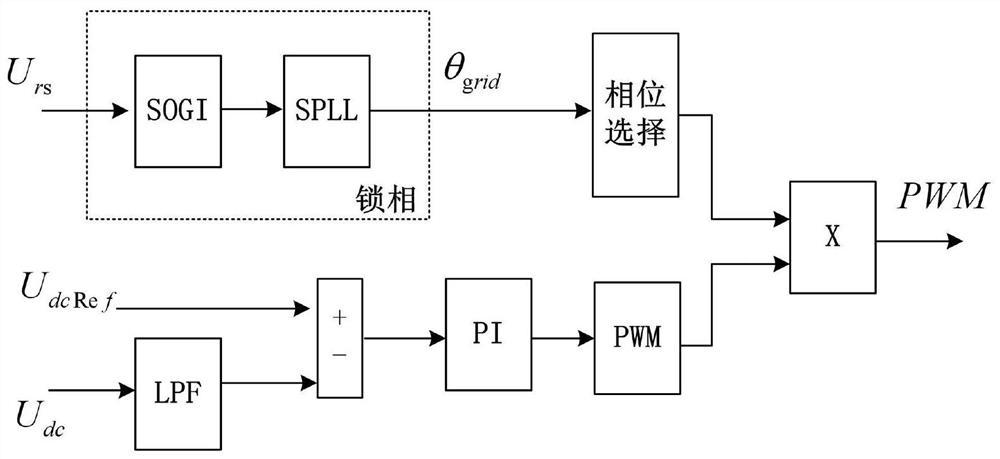
[0026] Example 2, such as figure 2 As shown, in order to realize the controllability of the output voltage, it is necessary to introduce closed-loop control. After the collected feedback Udc is low-pass filtered LPF, compared with the given voltage UdcRef, it enters the PI controller, and the result of the PI output generates a corresponding PWM Wave, the information of the power grid can be obtained through strict phase-locking for control. Urs in the figure is the RS line voltage in the three-phase input power supply, which uses a second-order generalized integrator (SOGI) and a software phase-locked loop (SPLL). Combined way to achieve phase-locking, to obtain the phase θ of the power grid grid , through phase control, the voltage area that needs to be chopped can be distinguished to achieve the purpose of rectifying and stepping down.

Embodiment 3

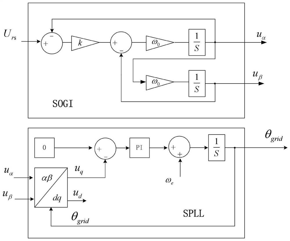
[0027] Example 3, such as image 3 As shown, it is the process of software phase-locking, where in SOGI, k is the adjustment proportional coefficient, ω 0 is the SOGI resonant frequency, and the quadrature voltage component u can be obtained after integration respectively α , u β , which is used for the software phase-locked loop control of the next level. After Park transformation, the DC component voltage Ud and Uq are obtained. Using the software phase-locked idea, the q-axis voltage is controlled to be 0, in the figure ω e is the frequency of the grid voltage, which can speed up the convergence process of the phase-locked loop. Usually, we need to convert it into a transfer function in the continuous domain, as shown in Equation 1, and then use the bilinear transformation method to discretize it.

[0028]

[0029]


PUM


Abstract

The invention discloses a brake power supply for a construction hoist and a control method. The brake power supply comprises a 380V power supply, a switch S1, a switch S2, a rectification module, an IGBT switch Q1, an IGBT switch Q2, an IGBT switch Q3, an IGBT switch Q4 and a diode, the 380V power supply is connected with the input end of the rectification module through the switch S1 and the switch S2, the output end + of the rectification module is connected with the drain electrode of the IGBT switch Q1, and the source electrode of the IGBT switch Q1 is connected with the diode and the drain electrode of the IGBT switch Q3. A design scheme different from a traditional brake power supply is adopted, and controllable rectification voltage reduction output voltage is achieved by designing a novel power electronic topological structure; and secondly, an independent chip is used for controlling and protecting the brake power supply, so that the stability and the safety of brake control are improved. Particularly, in the aspect of software control, stable and reliable direct-current output voltage is realized by adopting a more accurate closed-loop control mode.

Description

technical field [0001] The invention relates to the technical field of power supply control, in particular to a braking power supply and a control method for a construction elevator. Background technique [0002] At present, construction elevators used in buildings are mostly driven by asynchronous motors, and the upper and rear ends of the mechanical mechanism of the asynchronous motors are equipped with reducers and brakes. The brake control of the construction elevator is particularly critical. If there is a problem with the brake at the end of the motor, such as insufficient braking torque, it will cause the construction elevator to slip. The all-in-one driving machine of the construction hoist needs to reasonably control the switch of the brake, so as to realize the smooth and safe operation of the construction hoist. Usually, the brake at the tail end of the construction elevator motor is switched by switching on and off the DC power supply, and the input power of the...

Claims


Application Information

Patent Timeline
Patent Type & Authority Applications(China)
IPC IPC(8): H02M5/458H02P27/08
CPCH02M5/4585H02P27/085
Inventor 周稳马鑫
Owner 长沙市日业电气有限公司
Why Eureka
Try Eureka