
Cutting equipment convenient to adjust and used for automatic machining of printer parts

A technology for printers and parts, applied in the field of easy-to-adjust cutting equipment for automatic processing of printer parts, which can solve problems such as equipment damage, no shock absorption function, and low practicability

Pending Publication Date: 2021-10-26
深圳市通强数控科技有限公司
View PDF0 Cites 0 Cited by
  • Summary
  • Abstract
  • Description
  • Claims
  • Application Information

AI Technical Summary

Problems solved by technology

[0004] (1) The existing cutting equipment that is easy to adjust for automatic processing of printer parts is inconvenient to adjust the position of the parts to be cut. It takes a long time to adjust the position and has low practicability
[0005] (2) The existing easy-to-adjust cutting equipment for automatic processing of printer parts does not have a good shock absorption function, which is easy to cause damage to the equipment during the cutting process and has a short service life
[0006] (3) The cutting effect of the existing easy-to-adjust cutting equipment for automatic processing of printer parts is not ideal, and the cutting effect on fine parts is poor

Method used


Image

  • Cutting equipment convenient to adjust and used for automatic machining of printer parts
  • Cutting equipment convenient to adjust and used for automatic machining of printer parts
  • Cutting equipment convenient to adjust and used for automatic machining of printer parts

Examples


Embodiment Construction

[0029] The technical solutions in the embodiments of the present invention will be clearly and completely described below in conjunction with the accompanying drawings in the embodiments of the present invention. Obviously, the described embodiments are only some of the embodiments of the present invention, not all of them. Based on The embodiments of the present invention and all other embodiments obtained by persons of ordinary skill in the art without making creative efforts belong to the protection scope of the present invention.

[0030] In the description of the present invention, it should be noted that the terms "upper", "lower", "inner", "outer", "front end", "rear end", "both ends", "one end", "another end" The orientation or positional relationship indicated by etc. is based on the orientation or positional relationship shown in the drawings, and is only for the convenience of describing the present invention and simplifying the description, rather than indicating or...


PUM


Abstract

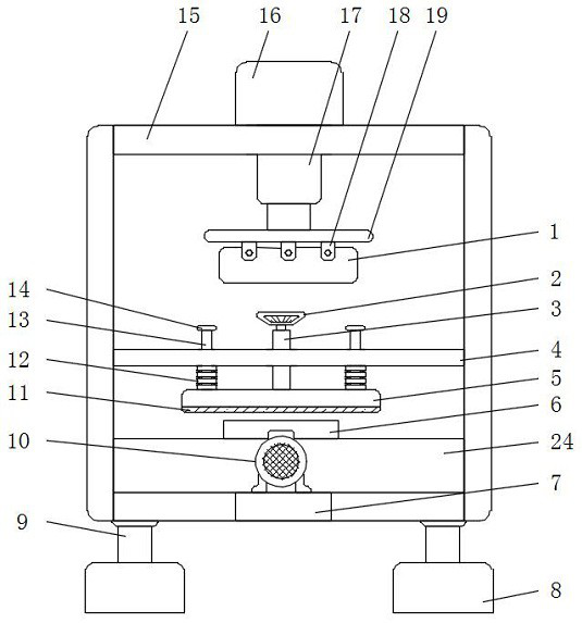
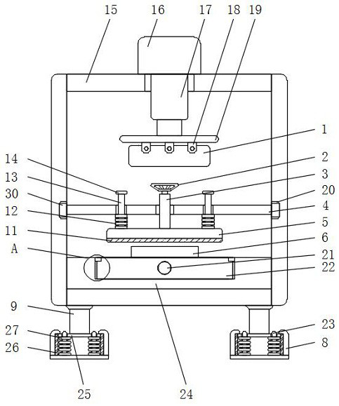
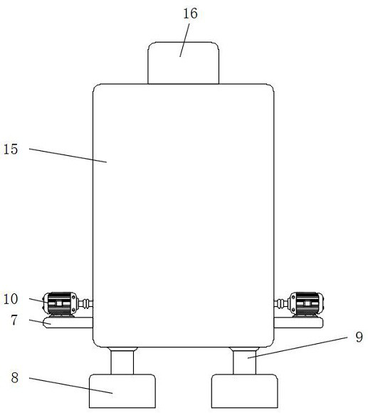
The invention discloses cutting equipment convenient to adjust and used for automatic machining of printer parts. The cutting equipment comprises a first threaded rod, a pressing plate, a positioning rod, a shell, a limiting rod and an operation base table, supporting legs are installed at the four corners of the bottom of the shell, extrusion plates are installed at the bottoms of the supporting legs, a damping rubber pad is installed on the outer wall of each extrusion plate, the damping rubber pads are installed on the inner wall of the base, limiting rods are evenly installed on the inner wall of the bottom of the base, the other ends of the limiting rods penetrate through the upper surfaces of the extrusion plates and extend to the outside of the base, a hydraulic cylinder is installed on the upper surface of the shell, a hydraulic telescopic rod is installed in the center of the bottom of the hydraulic cylinder, and the other end of the hydraulic telescopic rod penetrates through the upper surface of the shell to be provided with a push plate. The position adjustment work of a to-be-machined part can be achieved, the equipment has a good damping function, the service life is prolonged, and meanwhile the equipment is good in cutting effect and high in practicability.

Description

technical field [0001] The invention relates to the technical field of cutting equipment, in particular to an easily adjustable cutting equipment for automatic processing of printer parts. Background technique [0002] The printer is one of the output devices of the computer. It is used to print the computer processing results on the relevant media. There are three indicators to measure the quality of the printer: printing resolution, printing speed and noise. There are many types of printers. There are striking actions, which are divided into impact printers and non-impact printers. According to the structure of printed characters, they can be divided into full-width character printers and dot-matrix character printers. [0003] However, the cutting equipment that is convenient to adjust for the existing automatic processing of printer parts has the following defects: [0004] (1) The existing automatic cutting equipment for automatic processing of printer parts is inconve...

Claims


Application Information

Patent Timeline
Patent Type & Authority Applications(China)
IPC IPC(8): B26D7/01B26D7/02B26D7/22B26D1/06B26D5/12F16F15/08
CPCB26D7/01B26D7/02B26D7/22B26D1/06B26D5/12F16F15/085
Inventor 甄洁萍马哲翰
Owner 深圳市通强数控科技有限公司
Learn More