Grouting device for hydraulic engineering construction

A technology of water conservancy projects and reciprocating devices, applied in water conservancy projects, cement mixing devices, sea area projects, etc., can solve the problems of not being able to prefabricate grout, affecting grouting efficiency and quality, and low grouting efficiency, so as to increase grouting efficiency and quality, and facilitate The effect of changing the grout concentration and increasing the grouting efficiency

Inactive Publication Date: 2021-10-26
付建利
View PDF0 Cites 4 Cited by
  • Summary
  • Abstract
  • Description
  • Claims
  • Application Information

AI Technical Summary

Problems solved by technology

[0003] The existing grouting device for water conservancy construction mainly consists of a stirring device, a pressurizing device, and a grouting device. The material is added to the stirring device, and then the stirring device is turned on, and then the stirring device mixes water and aggregate to form a slurry, and then the pressure device presses the slurry into the grouting device, and then the grouting device presses the slurry into the drill hole for grouting , but the process of artificially taking water and aggregate according to the proportion of ingredients is relatively cumbersome, and the workload is large. It is easy to cause large errors in the concentration of grout due to operational errors, which affects the efficiency and quality of grouting. Moreover, the grout cannot be prefabricated, and it is inconvenient to change the concentration of the grout. In the process of changing the grout concentration, the grouting process is likely to be interrupted, resulting in low grouting efficiency. At the same time, artificially adding the aggregate to the water at one time will easily cause the aggregate to form agglomerates, and it is difficult to form a homogeneous grout. Therefore, it is urgent to design a water conservancy project. grouting device

Method used


Image

  • Grouting device for hydraulic engineering construction
  • Grouting device for hydraulic engineering construction
  • Grouting device for hydraulic engineering construction

Examples


Embodiment Construction

[0035] The technical solutions in the embodiments of the present invention will be clearly and completely described below in conjunction with the accompanying drawings in the embodiments of the present invention; obviously, the described embodiments are only some embodiments of the present invention; rather than all embodiments. Based on the embodiments of the present invention; all other embodiments obtained by persons of ordinary skill in the art without creative work; all belong to the protection scope of the present invention.

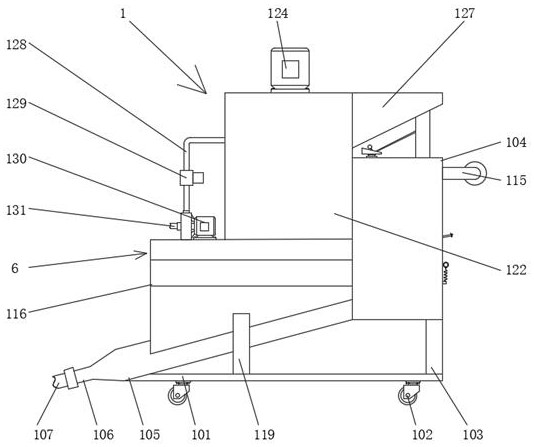
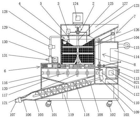
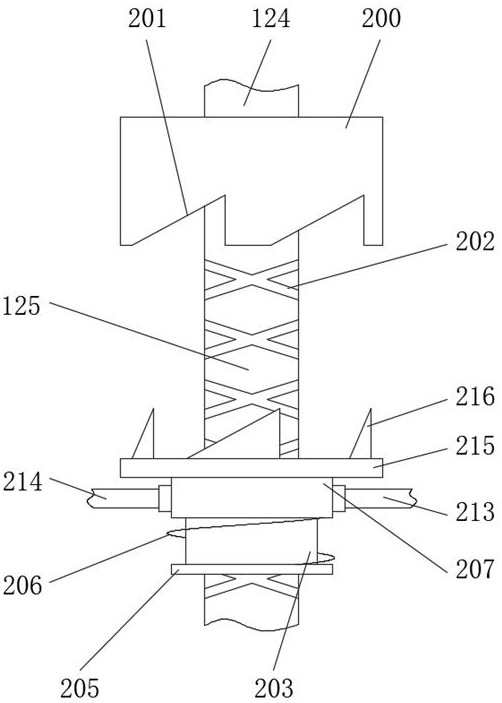
[0036] see Figure 1-13 , a grouting device for water conservancy construction, comprising a pulping device 1, the inside of the pulping device 1 is provided with an up and down reciprocating device 2.

[0037]The pulping device 1 comprises a load-carrying plate 101, a universal wheel 102 is fixedly installed on the bottom surface of the load-carrying plate 101, and a right reinforcement column 103 is fixedly connected to the top surface of the loa...


PUM


Abstract

The invention discloses a grouting device for hydraulic engineering construction. The grouting device comprises a pulping device, wherein an up-down reciprocating device is arranged in the pulping device. Through the pulping device, the grouting device can prefabricate slurry in advance, the concentration of the slurry is convenient to change, the situation that the grouting process is interrupted due to the change of the concentration of the slurry is avoided, and the grouting efficiency is improved; through the cooperation of the pulping device, the up-down reciprocating device, a weighing device, an accommodating device and a linkage device, the grouting device can detect the concentration of the prefabricated slurry in real time, water and aggregate with specified proportional quantity do not need to be manually measured, the workload is small, the accuracy is high, and the grouting efficiency and quality are improved; and through a discharging device, the prefabricated slurry can be put into grouting operation; through the cooperation of the pulping device, a beating device and a transmission device, the aggregate can be gradually scattered into water in a waterfall mode, the water and the aggregate can form homogeneous slurry, and the practicability of the grouting device for hydraulic engineering construction is improved.

Description

technical field [0001] The invention relates to the field of water conservancy project grouting equipment, in particular to a water conservancy project construction grouting device. Background technique [0002] Water conservancy engineering is a project built to control and allocate natural surface water and groundwater to achieve the purpose of eliminating harm and rejuvenating profits. It is also called water engineering. Water is an indispensable and precious resource for human production and life, but its natural existence The state does not fully meet the needs of human beings. Only by building water conservancy projects can water flow be controlled, floods prevented, and water volume adjusted and distributed to meet the needs of people's life and production for water resources. Water conservancy projects require the construction of dams, dikes, Spillways, sluices, water inlets, canals, crossings, rafts, fishways and other types of hydraulic structures, in order to ach...

Claims


Application Information

Patent Timeline
Patent Type & Authority Applications(China)
IPC IPC(8): E02D15/02E02D3/12E02B3/16B28C5/16B28C7/04B28C7/06B28C7/12
CPCE02D15/02E02D3/12E02B3/16B28C5/16B28C7/0481B28C7/067B28C7/126
Inventor 付建利陈忠刘晓张超路玉恒
Owner 付建利
Why Eureka
Try Eureka