Heat accumulating type energy-saving boiler

A regenerative boiler technology, applied in steam boilers, boiler cleaning devices, cleaning heat transfer devices, etc., can solve the problems of low heating water efficiency, waste of heat energy, etc., and achieve the effect of quick cleaning and avoiding excessive dirt

Inactive Publication Date: 2021-10-26
NANJING VOCATIONAL UNIV OF IND TECH
View PDF1 Cites 0 Cited by
  • Summary
  • Abstract
  • Description
  • Claims
  • Application Information

AI Technical Summary

Problems solved by technology

[0003] At present, the hot gas generated during the combustion of the boiler will be directly discharged into the air, and the direct discharge of the hot gas into the air will cause a waste of heat energy. Accumulation can cause boilers to be less efficient at heating water
[0004] Chinese patent discloses an energy-saving boiler (Notice No. CN108488824A). The exhaust gas produced by the combustion of coal in the combustion chamber of this patent technology is discharged from the chimney. After passing through the filter device, the tail gas is treated and discharged, which reduces the degree of damage to the filter device caused by the exhaust gas due to excessive temperature, and increases the service life of the filter device. However, this patent discharges the hot gas generated by the boiler into the air. cause waste of heat

Method used


Image

  • Heat accumulating type energy-saving boiler
  • Heat accumulating type energy-saving boiler
  • Heat accumulating type energy-saving boiler

Examples


Embodiment 1

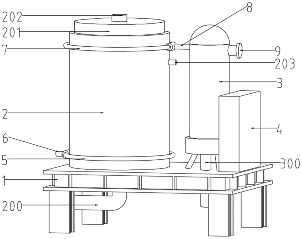
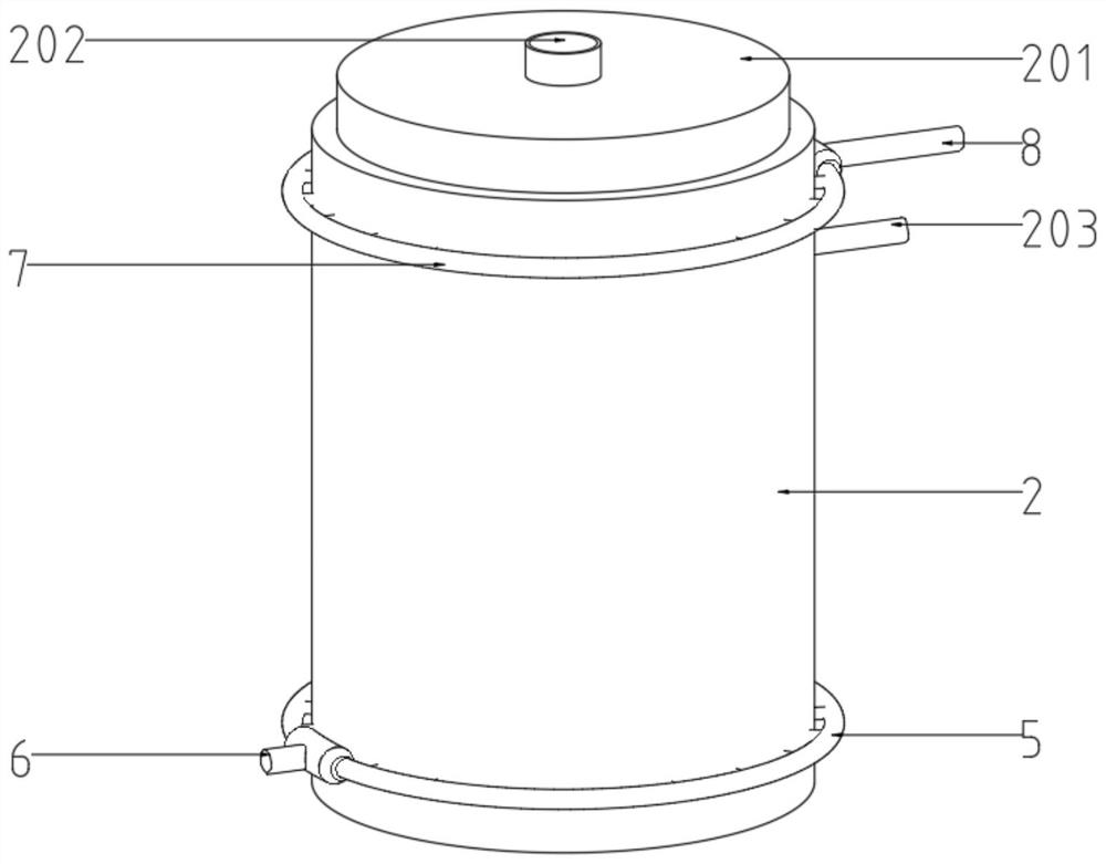
[0029] see Figure 1~3 , in an embodiment of the present invention, a regenerative energy-saving boiler includes a base 1, a furnace body 2, a water vapor separator 3, and a control box 4. The upper end of the furnace body 2 is provided with a first smoke collection chamber 201, and the first smoke collection chamber The upper end of the chamber 201 is provided with a smoke exhaust port 202, and the outside of the furnace body 2 is provided with a water inlet pipe 5, which is sleeved at the lower half of the furnace body 2, and the left end of the water inlet pipe 5 is provided with a water inlet 6. The water inlet 6 can be connected to external water supply equipment. The outside of the furnace body 2 is also provided with a water outlet pipe 7. The water outlet pipe 7 is located above the water inlet pipe 5. The water outlet pipe 7 is connected to the water vapor separator 3 through a transition pipe 8. The water vapor separator The right end of 3 is provided with a gas outl...

Embodiment 2

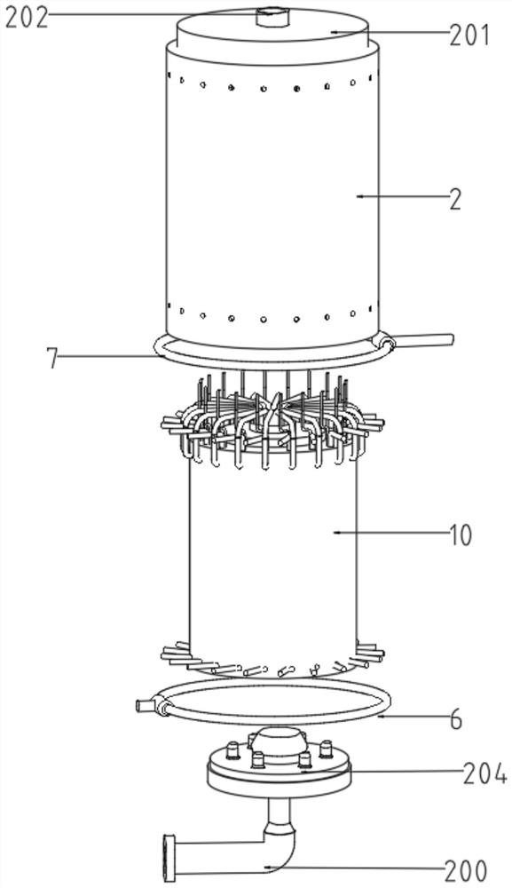
[0031] see Figure 4 , 5 , 6, 7, combined with the basis of embodiment 1, the heating structure includes several smoke guide pipes 101 and some heating pipes 102, the heating structure is composed of several smoke guide pipes 101 and heating pipes 102, and the smoke guide pipes 101 are wrapped in the heating pipe 102 Externally, the smoke guide pipe 101 is composed of two square pipes, which are connected by the second connecting pipe 110, and the ends of the two square pipes close to each other are provided with arc-shaped grooves, and the arc-shaped grooves are connected with the heating pipe 102 correspond to each other, the upper and lower ends of the heating pipe 102 are provided with connecting water pipes 103, the connecting water pipes 103 at the upper and lower ends of the heating pipe 102 are respectively located on the upper and lower sides of the smoke guide pipe 101, and the connecting water pipes 103 at the upper and lower ends of the heating pipe 102 respectivel...

Embodiment 3

[0033] see Figure 8 , 9 , in conjunction with the basis of embodiment 2, the inside of heating tube 102 is provided with heating inner tube 111, is provided with some reinforcing ribs 113 between heating inner tube 111 and heating tube 102, is provided with some round holes on some reinforcing ribs 113, heating The inner tube 111 is provided with a number of connectors 112 through the tube wall, and the plurality of connectors 112 are respectively located between the reinforcing ribs 113. The inside of the heating inner tube 111 is provided with a metal sleeve 114. The metal sleeve 114 is made of thin copper sheet. Several connecting plates 115 are provided between the sleeve 114 and the heating inner tube 111 , and the metal sleeve 114 is connected to the heating inner tube 111 through the connecting plates 115 .

[0034] The working principle of the present invention is:

[0035]When the present invention is in use, the combustion disc 204 is opened to heat the inside of ...


PUM


Abstract

The invention discloses a heat accumulating type energy-saving boiler, and belongs to the technical field of boiler equipment. The heat accumulating type energy-saving boiler comprises a base, a boiler body, a water-steam separator and a control box, a first smoke collecting chamber is arranged at the upper end of the boiler body, a smoke outlet is formed in the upper end of the first smoke collecting chamber, the boiler body is sleeved with a water inlet pipe, and the boiler body is further sleeved with a water outlet pipe. Hot air generated by heating a combustion cover by a combustion disc enters a second smoke collecting chamber, the hot air entering the second smoke collecting chamber enters a smoke guide pipe through a first connecting pipe, and the hot air entering a smoke guide pipe flows in the smoke guide pipe, then is discharged to the first smoke collecting chamber through a smoke outlet pipe, and finally is discharged through the smoke outlet; and when the hot air generated when the combustion cover is heated by the combustion disc flows in the smoke guide pipe, a heating pipe can be further heated and subjected to heat preservation, in this way, the heating speed of water in the heating pipe can be increased, and meanwhile, the hot air can be prevented from being directly discharged, so that waste of heat energy is avoided.

Description

technical field [0001] The invention relates to the technical field of boiler equipment, in particular to a regenerative energy-saving boiler. Background technique [0002] The boiler is a kind of energy conversion equipment. The energy input to the boiler includes chemical energy and electric energy in the fuel, and the boiler outputs steam, high-temperature water or organic heat carrier with a certain amount of heat energy. [0003] At present, the hot gas generated during the combustion of the boiler will be directly discharged into the air, and the direct discharge of the hot gas into the air will cause a waste of heat energy. Buildup can cause the boiler to become less efficient at heating water. [0004] Chinese patent discloses an energy-saving boiler (Notice No. CN108488824A). The exhaust gas produced by the combustion of coal in the combustion chamber of this patent technology is discharged from the chimney. After passing through the filter device, the tail gas is...

Claims


Application Information

Patent Timeline
Patent Type & Authority Applications(China)
IPC IPC(8): F22B1/22F22B31/08F22B37/26F22B37/50F22B37/54F23J15/06F28G1/12
CPCF22B1/22F22B31/08F22B37/26F22B37/54F22B37/50F23J15/06F28G1/12Y02E20/30
Inventor 满毅
Owner NANJING VOCATIONAL UNIV OF IND TECH
Why Eureka
Try Eureka