Suction nozzle detection method, system and device, and storage medium

A detection method and technology for detecting data, applied in transmission systems, manufacturing computing systems, digital transmission systems, etc., can solve the problems of low detection efficiency, high detection cost, flying materials, etc., to avoid unnecessary losses, improve detection accuracy, The effect of shortening the detection time

Active Publication Date: 2021-10-26
JIUJIANG JIAYUAN TECH
View PDF11 Cites 0 Cited by
  • Summary
  • Abstract
  • Description
  • Claims
  • Application Information

AI Technical Summary

Problems solved by technology

Since the front end of the commonly used suction nozzle is small, generally within 0.6*0.6mm, and the suction nozzle is a part that directly contacts the components, it is prone to wear and tear during the contact with the components, resulting in the suction of the suction nozzle being affected
The use of problematic nozzles for production may cause material throwing, flying materials, etc., which directly affect the placement quality, so the inspection of the placement machine nozzles is particularly critical
[0003] The inventor found in the process of implementing the present invention that due to the small front end of the suction nozzle, in the existing detection method of the suction nozzle, in order to obtain a more reliable detection result, the methods generally adopted include: (1) improving the accuracy of the detection equipment, However, the cost of equipment replacement and inspection is high; (2) Multiple inspections are performed on the suction nozzle, so as to reduce the detection error by analyzing multiple sets of data, but it will cause more unnecessary wear and tear on the suction nozzle and prolong the detection time. The time required, the detection efficiency is low

Method used


Image

  • Suction nozzle detection method, system and device, and storage medium
  • Suction nozzle detection method, system and device, and storage medium
  • Suction nozzle detection method, system and device, and storage medium

Examples


Embodiment Construction

[0038] Below, the present invention will be further described in conjunction with the accompanying drawings and specific implementation methods. It should be noted that, under the premise of not conflicting, the various embodiments described below or the technical features can be combined arbitrarily to form new embodiments. .

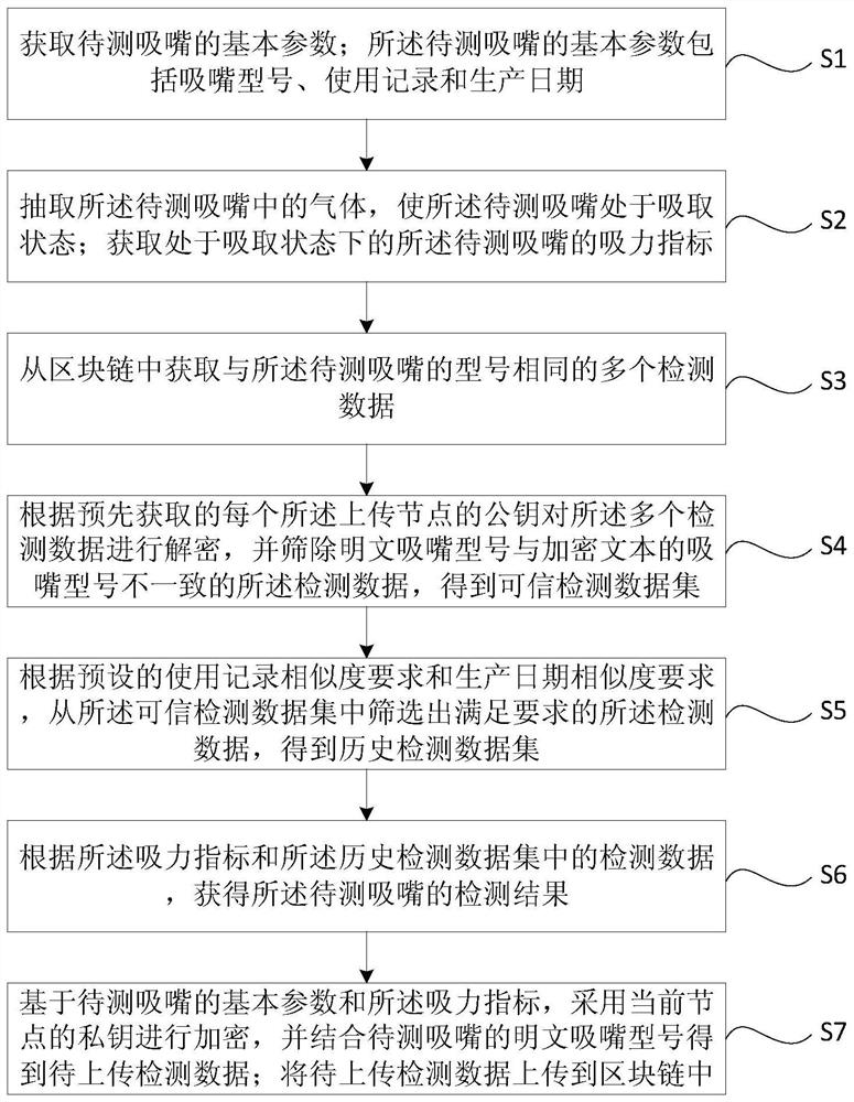
[0039] The first embodiment of the present invention provides a nozzle detection method. see figure 1 The nozzle detection method includes steps S1 to S6, preferably, step S7 may also be included.

[0040] S1. Obtain the basic parameters of the suction nozzle to be tested; the basic parameters of the suction nozzle to be tested include the nozzle model, use record and production date.

[0041] Wherein, the basic parameters of the suction nozzle to be tested can be manually input by the user, or can be pre-stored in a database, and the basic parameters of the suction nozzle to be tested in the database can be acquired when step S1 is executed.

[004...


PUM


Abstract

The embodiment of the invention discloses a suction nozzle detection method. The method comprises the following steps: acquiring basic parameters of a to-be-detected suction nozzle; extracting gas in the to-be-detected suction nozzle to enable the suction nozzle to be in a suction state, and obtaining a suction force index; obtaining multiple pieces of detection data from a block chain with a same model as the to-be-detected suction nozzle; decrypting the multiple pieces of detection data according to a pre-acquired public key of each uploading node, and screening out detection data of which the suction nozzle model of plaintext is inconsistent with the suction nozzle model of an encrypted text so as to obtain a credible detection data set; according to preset use records and a production date similarity requirement, screening detection data meeting requirements to obtain a historical detection data set; obtaining a detection result according to the suction force index and detection data in the historical detection data set. The embodiment of the invention further provides a suction nozzle detection system and device, and a storage medium, so that the detection precision can be satisfied while the suction nozzle detection efficiency is effectively improved, and rapid and accurate suction nozzle detection is achieved.

Description

technical field [0001] The invention relates to the technical field of detection of suction nozzles of chip mounters, in particular to a method, system, equipment and storage medium for detection of suction nozzles. Background technique [0002] In the production process of the chip, the placement machine of the chip production line absorbs the components through the suction nozzle and then mounts them on the printed circuit board. The working status of the suction nozzle directly affects the placement quality. Since the front end of the commonly used suction nozzle is small, generally within 0.6*0.6mm, and the suction nozzle is a part that directly contacts the components, it is prone to wear and tear during the contact with the components, which affects the suction of the suction nozzle. The use of problematic nozzles for production may cause material throwing, flying materials, etc., which directly affect the placement quality, so the inspection of the placement machine n...

Claims


Application Information

Patent Timeline
Patent Type & Authority Applications(China)
IPC IPC(8): G06F16/27G06F21/60G06Q10/06G06Q50/04H04L29/06H04L29/08
CPCG06F16/27G06F21/602G06Q10/06393G06Q10/0637G06Q50/04H04L63/0428H04L67/12H04L9/50Y02P90/30
Inventor 冯斌冯韵涵
Owner JIUJIANG JIAYUAN TECH
Why Eureka
Try Eureka