Output Matching Module, Doherty Power Amplifier

An output matching and inductor technology, used in power amplifiers, amplifiers, and improving amplifiers to improve efficiency. , enhance the effect of miniaturization

Active Publication Date: 2021-12-07
ZTE CORP
View PDF4 Cites 0 Cited by
  • Summary
  • Abstract
  • Description
  • Claims
  • Application Information

AI Technical Summary

Problems solved by technology

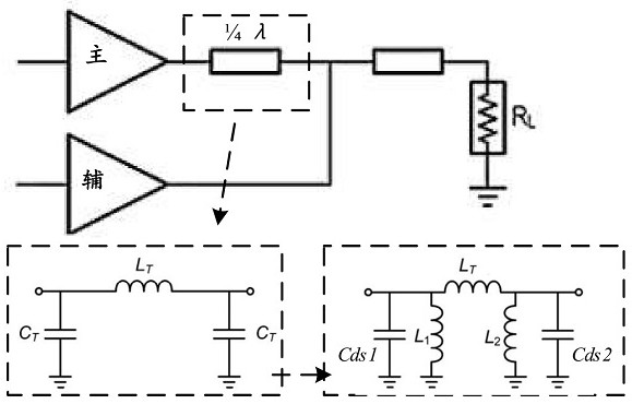
In order to reduce the size, the current Doherty power amplifier generally outputs the 1 / 4 wavelength impedance transformation line in the output matching network (ie figure 1 The middle 1 / 4λ line) is equivalent to a lumped C-L-Cπ network, such as figure 1 As shown, the 1 / 4 wavelength impedance transformation line is equivalent to including the inductance L T and two capacitors C T The network composed of lumped C-L-Cπ type network includes: inductor L T , inductance L 1 , inductance L 2 , The parasitic drain-source capacitance Cds1 of the main circuit chip and the parasitic drain-source capacitance Cds2 of the auxiliary circuit chip, since the parameter values ​​of all circuit components in the lumped C-L-Cπ network are unique, when the circuit components are integrated into the chip , if the available space of the chip is limited, it may not be realized, that is to say, directly applying the lumped C-L-Cπ network to realize the chip will not be able to miniaturize

Method used


Image

  • Output Matching Module, Doherty Power Amplifier
  • Output Matching Module, Doherty Power Amplifier
  • Output Matching Module, Doherty Power Amplifier

Examples


Embodiment Construction

[0021] In order for those skilled in the art to better understand the technical solution of the present application, the output matching module and the power amplifier provided by the present application will be described in detail below with reference to the accompanying drawings.

[0022] Example embodiments will be described more fully hereinafter with reference to the accompanying drawings, but may be embodied in different forms and should not be construed as limited to the embodiments set forth herein. Rather, these embodiments are provided so that this application will be thorough and complete, and will fully convey the scope of the application to those skilled in the art.

[0023] In the case of no conflict, each embodiment of the present application and each feature in the embodiment can be combined with each other.

[0024] As used herein, the term "and / or" includes any and all combinations of at least one of the associated listed items.

[0025] The terminology used...


PUM


Abstract

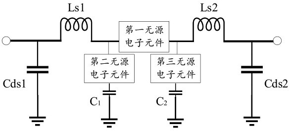
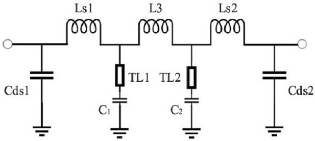
The present application provides an output matching module and a Doherty power amplifier. The output matching module includes: a first inductor, a second inductor, a first passive electronic component, a second passive electronic component, a third passive electronic Components, a first DC-blocking capacitor, and a second DC-blocking capacitor; wherein, one end of the first inductor is connected to the drain of the main circuit die, and the other end of the first inductor is connected to one end of the second passive electronic component; The other end of the second passive electronic component is grounded through the first DC blocking capacitor; one end of the second inductor is connected to the drain of the auxiliary circuit die, and the other end of the second inductor is connected to one end of the third passive electronic component; The other end of the third passive electronic component is grounded through the second DC blocking capacitor; the other end of the second passive electronic component or the third passive electronic component is connected to a bias power supply; one end of the first passive electronic component is connected to the first inductor The other end of the inductor is connected, and the other end of the first passive electronic component is connected to the other end of the second inductor.

Description

technical field [0001] The embodiments of the present application relate to the field of microwave power amplifiers, in particular to output matching modules and Doherty power amplifiers. Background technique [0002] In order to meet the increasing demands of high data transmission rate and spectrum efficiency in the field of wireless communication, wider frequency bands, more complex modulation methods, and more channels are introduced. Complex modulation methods require the power amplifier to amplify the peak-to-average ratio signal. In order to meet the linearity requirements of the peak-to-average ratio signal, the power amplifier needs to work in the back-off state most of the time, which will bring about a significant decrease in back-off efficiency. The number of channels The increase of back-off efficiency also needs to be improved to reduce power consumption and heat dissipation. Currently, technologies that can improve back-off efficiency include envelope tracking...

Claims


Application Information

Patent Timeline
Patent Type & Authority Patents(China)
IPC IPC(8): H03F1/56H03H7/38H03F1/07H03F3/22
CPCH03F1/565H03H7/38H03F1/07H03F3/22
Inventor 吕肖林张煜崔凯
Owner ZTE CORP
Why Eureka
Try Eureka