Transcatheter heart annuloplasty system

A heart valve ring and catheter technology, applied in the field of medical devices, can solve problems such as increasing operation time and reducing heart pumping efficiency, and achieve the effect of avoiding operation difficulty, avoiding secondary operation correction, and reducing operation and physical strength requirements

Active Publication Date: 2021-10-29
上海御瓣医疗科技有限公司
View PDF8 Cites 6 Cited by
  • Summary
  • Abstract
  • Description
  • Claims
  • Application Information

AI Technical Summary

Problems solved by technology

Mitral regurgitation (MR) in mitral valve disease has a very serious impact on patients. Under normal circumstances, the mitral valve in the human heart acts as a hemostatic valve, preventing oxygen-rich blood from the lungs from returning to the left atrium. In the middle, once the mitral valve is improperly closed or misplaced, MR will occur, which will significantly reduce the pumping efficiency of the heart and even cause heart failure
[0004] The current annuloplasty devices have the following problems: (1) The take-up device used can only tighten the annulus in one direction. Once it is over-contracted, it can only rely on the self-tension of the annulus to provide a reverse force to drive the contraction shaft. To achieve the purpose of adjusting the degree of shrinkage; (2) The screw needs to be delivered individually, and the delivery device can only deliver one screw at a time. After screwing in, it needs to be withdrawn and loaded with the next screw before continuing to deliver and screw in, which increases the operation time

Method used


Image

  • Transcatheter heart annuloplasty system
  • Transcatheter heart annuloplasty system
  • Transcatheter heart annuloplasty system

Examples


Embodiment Construction

[0042] In this article, "proximal end" refers to the end of the medical device close to the doctor when the doctor is using the medical device; "distal end" refers to the end of the medical device away from the doctor when the doctor is using the medical device; this term is consistent with medical device A customary practice in the industry.

[0043] A transcatheter heart annuloplasty system comprising

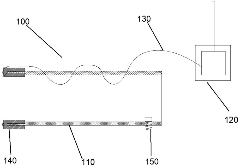
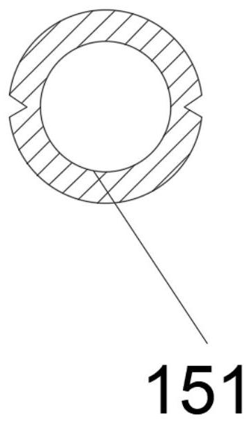
[0044] The forming ring assembly 100, the forming ring assembly 100 includes a polymer braided tube 110, an anchor 150, a shrinking wire 130 and a bidirectional shrinking device 120;

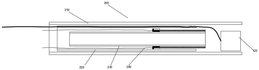
[0045] a delivery assembly 200 for delivering the forming ring assembly 100 to a target location;

[0046] The continuous anchor assembly 300 is used to fix the forming ring assembly 100 at a target position.

[0047] The forming ring assembly 100 includes

[0048] A polymer braided tube 110, the polymer braided tube 110 is configured as a tubular structure with a closed distal end;

[0049...


PUM


Abstract

The invention belongs to the technical field of medical instruments and particularly relates to the technical field of interventional instruments in third-class medical instruments, in particular to a transcatheter heart annuloplasty system. The transcatheter heart annuloplasty system comprises a forming ring assembly, wherein the forming ring assembly comprises a macromolecular braided tube, an anchor nail, a contraction line and a bidirectional contraction device; a delivery assembly, wherein the delivery assembly is used for conveying the forming ring assembly to a target position; and a continuous anchoring assembly, wherein the continuous anchoring assembly is used for fixing the forming ring assembly to the target position. Through the bidirectional contraction device based on a compression spring, a friction disc and a wire spool, bidirectional contraction of a forming ring fixed to a valve is achieved, the strength and size of contraction of the valve are accurately adjusted, locking can be achieved at any time, a doctor is allowed to adjust the contraction degree of the valve according to different conditions of different patients, and the doctor is allowed to make adjustment in an opposite direction, so that the size change of the valve during continuous opening and closing is adapted, thus, the success rate of an operation is guaranteed, and secondary operation correction is avoided.

Description

technical field [0001] The invention belongs to the technical field of medical devices, in particular to the technical field of interventional devices in the third category of medical devices, and in particular to a transcatheter heart valve annuloplasty system. Background technique [0002] Minimally invasive interventional medical technology is an efficient diagnosis and treatment method that has gradually emerged in recent years. It has outstanding advantages such as small trauma, easy operation, accurate intervention site, and few complications. It has become one of the most important diagnostic and treatment methods for cardiovascular diseases and tumor diseases. . In interventional medical operations, professional doctors usually need to manually operate specific devices to enable one or more slender flexible catheters with different shapes or functions to pass through the patient's complex and changeable cardiovascular and other human body cavity environment, and guid...

Claims


Application Information

Patent Timeline
Patent Type & Authority Applications(China)
IPC IPC(8): A61F2/24
CPCA61F2/2436A61F2/2448A61F2/246A61F2/2466
Inventor 李建文李峰
Owner 上海御瓣医疗科技有限公司
Why Eureka
Try Eureka