
Gearbox shaft forge piece machining equipment and machining method thereof

A technology for processing equipment and gearboxes, which is applied in the field of shaft forgings, can solve the problems affecting the service life of shaft forgings' mechanical properties, low automation and production efficiency, and inability to perform thermal correction at the same time, so as to improve mechanical performance and service life. High degree of automation and production efficiency, the effect of shortening the forging time

Pending Publication Date: 2021-10-29
ZHEJIANG JIAJIE AUTOMOBILE DESIGN CO LTD
View PDF8 Cites 0 Cited by
  • Summary
  • Abstract
  • Description
  • Claims
  • Application Information

AI Technical Summary

Problems solved by technology

However, this solution still cannot perform thermal correction and flash cutting process at the same time, resulting in longer forging time of shaft forgings, which affects the mechanical properties and service life of shaft forgings. There are defects of low degree of automation and production efficiency

Method used


Image

  • Gearbox shaft forge piece machining equipment and machining method thereof
  • Gearbox shaft forge piece machining equipment and machining method thereof

Examples


Embodiment 1

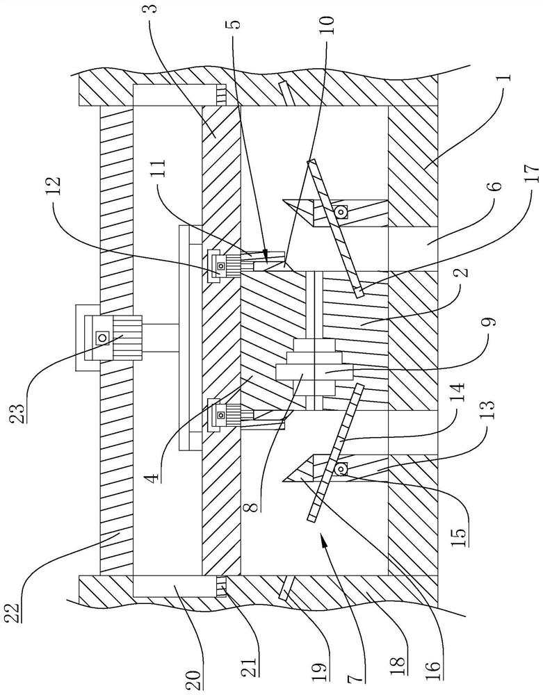
[0027] Such as Figure 1-2 As shown, a gearbox shaft forging processing equipment includes a processing base 1. The processing base 1 is provided with a thermally corrected shaft forging lower die 2. Above the thermally corrected shaft forging lower die 2 is a The upper mold fixed plate 3 that reciprocates linearly in the vertical direction, the bottom of the upper mold fixed plate 3 is provided with a heat correction shaft forging upper mold 4, and the bottom of the upper mold fixed plate 3 is also provided with a number of upper mold fixed plates 3 An automatic flash cutting assembly 5 symmetrical to the center line. The automatic flash cutting assembly 5 is slidably matched with the upper die 4 of the heat-corrected shaft forging. The material chute 6 , between the said material falling chute 6 and the automatic flash cutting assembly 5 , there is an edge material baffle member 7 which can reciprocate along a straight line.

[0028] In this embodiment, the upper die fixing...

Embodiment 2

[0048] Based on the transmission shaft forging processing equipment provided in Example 1, this embodiment provides a processing method using the transmission shaft forging processing equipment, including the following steps: S1: Place the shaft forging to be processed on the lower mold of the thermally corrected shaft forging In step 2, the upper die 4 of the thermally corrected shaft forging is brought closer to one end of the lower die 2 of the thermally corrected shaft forging, so that the lower die 2 of the thermally corrected shaft forging and the upper die 4 of the thermally corrected shaft forging are closely pressed together to perform thermal correction; S2: Move the automatic flash cutting assembly 5 downwards, automatically cut the flash of the shaft forging through the automatic flash cutting assembly 5, and the cut flash material falls on the edge material blocking plate 7; S3: complete the flash cutting Finally, by moving the edge material baffle plate 7, the fla...


PUM


Abstract

The invention belongs to the technical field of shaft forge piece forging, and particularly relates to gearbox shaft forge piece machining equipment and a machining method thereof. The gearbox shaft forge piece machining equipment comprises a machining base, the machining base is provided with a thermal correction shaft forging piece lower die, an upper die fixing plate capable of doing reciprocating rectilinear motion in the vertical direction is arranged above the thermal correction shaft forging piece lower die, and a thermal correction shaft forging piece upper die is arranged at the bottom of the upper die fixing plate. Through the arrangement of a flash removal cutter, a cutter limiting plate and a rim charge blocking and communicating plate, the shaft forging piece is subjected to thermal correction, meanwhile, flash of the shaft forging piece is automatically cut off through the flash removal cutter, the forging time of the shaft forging piece is shortened, the mechanical performance of the shaft forging piece is improved, and the service life of the shaft forging piece is prolonged; and through moving the rim charge blocking and communicating plate, the flash on the edge blocking and communicating plate can enter a discharging groove, the flash is automatically discharged through the discharging groove, the flash does not need to be manually cleaned, operation is easy and convenient, and the automation degree and the production efficiency are high.

Description

technical field [0001] The invention belongs to the technical field of shaft forging forging, and relates to a transmission shaft forging processing equipment and a processing method thereof. Background technique [0002] Forgings refer to workpieces or blanks obtained by forging and deforming metal blanks. By applying pressure to metal blanks to produce plastic deformation, their mechanical properties can be changed. Forgings can be divided into cold and cold according to the temperature of the blank during processing. Warm forging and hot forging, cold forging is generally processed at room temperature, hot forging is processed at a temperature higher than the recrystallization temperature of the metal blank, so that the shaft forging can be processed into a stepped shape, and the general shaft is Used as car parts. Among them, the gearbox shaft is also processed by hot forging. During the hot forging process of the gearbox shaft, flash cutting is required. Due to the def...

Claims


Application Information

Patent Timeline
Patent Type & Authority Applications(China)
IPC IPC(8): B21J9/02B21K1/06B21K27/06
CPCB21J9/02B21K1/06B21K27/06B21J13/02
Inventor 肖尚磊陈强钱志强
Owner ZHEJIANG JIAJIE AUTOMOBILE DESIGN CO LTD
Learn More