Mechanical manufacturing clamp

A technology of mechanical manufacturing and fixtures, which is applied in the field of mechanical manufacturing fixtures. It can solve the problems of large machining errors in the middle, affecting the accuracy of machining, and inconvenient adjustment of the main fixture, so as to achieve the effects of reducing errors, increasing friction, and reducing the number of times.

Inactive Publication Date: 2021-10-29
HENAN POLYTECHNIC INST
View PDF8 Cites 0 Cited by
  • Summary
  • Abstract
  • Description
  • Claims
  • Application Information

AI Technical Summary

Problems solved by technology

[0003] In the process of using the original mechanical manufacturing fixture, the main fixture is inconvenient to adjust, and it is not convenient for some processing that requires special angles, resulting in the need to change fixtures or machine tools back and forth, and repeated installation, which affects the processing accuracy and reduces work efficiency. When processing a long workpiece, the clamping force is limited, resulting in a large machining error in the middle. When rotating at high speed, the workpiece often has some shaking, which affects the processing accuracy.

Method used


Image

  • Mechanical manufacturing clamp
  • Mechanical manufacturing clamp
  • Mechanical manufacturing clamp

Examples


Embodiment

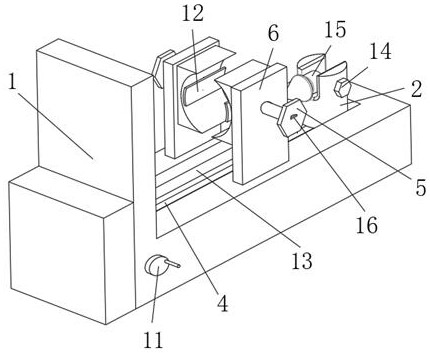
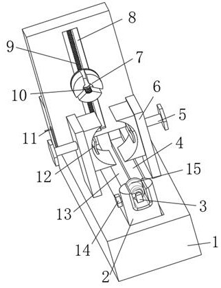
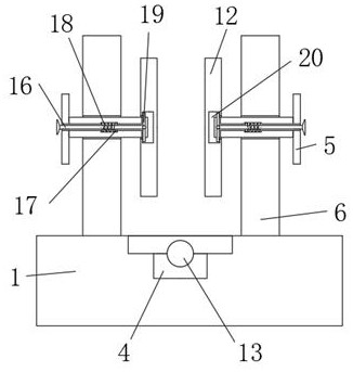
[0022] see Figure 1-5 , the present invention provides the following technical solutions: a fixture for mechanical manufacturing, including a main body 1, an adjustment block 2 and a support block 6, the main body 1 is provided with a sliding groove 8 for the rotation of the rack mechanism 9, and the sliding groove 8 is provided for The rotating shaft connected with the rocker 11, the rotating shaft of the sliding groove 8 is provided with a second gear mechanism 24 for connecting with the rack mechanism 9, the second gear mechanism 24 is connected with the main clamp 7 through the rack mechanism 9, the main body 1 There is a moving groove 4 for adjusting the moving effect of the adjusting block 2 inside. The moving groove 4 is provided with a screw rod 13 for adjusting the function of the adjusting block 2. The moving groove 4 is connected with the adjusting block 2 through the screw rod 13. The adjusting block 2 is provided with There is a rectangular slot for the rotation ...


PUM


Abstract

The invention belongs to the technical field of mechanical clamps, and particularly relates to a mechanical manufacturing clamp. The mechanical manufacturing clamp comprises a main body, an adjusting block and a supporting block, a sliding groove used for rotation of a rack mechanism is formed in the main body, a rotating shaft used for being connected with a rocker is arranged in the sliding groove, and a second gear mechanism used for being connected with the rack mechanism is arranged at the rotating shaft of the sliding groove. Through arrangement of the supporting block, the distance between supporting pieces is adjusted at the supporting block through locking rods, the supporting and fixing effects are achieved when some too long workpieces are machined, the offset effect caused by the too large center distance is effectively prevented, and the machining precision of the workpieces is improved; through arrangement of the adjusting block, the angle between the locking rods and connecting shafts is adjusted through T-shaped rods at the adjusting block, some machining surfaces with the inclined angle requirement can be conveniently machined, the problem of machine tool model replacement during workpiece machining is effectively avoided, errors caused by frequent machining and mounting are reduced, and the workpiece machining precision is ensured.

Description

technical field [0001] The invention belongs to the technical field of mechanical fixtures, and in particular relates to a mechanical manufacturing fixture. Background technique [0002] The device used to fix the processing object in the process of mechanical manufacturing so that it occupies the correct position to accept construction or inspection, also known as fixture. In a broad sense, in any process in the process, the device used to quickly, conveniently and safely install the workpiece can be called a fixture, such as welding fixtures, inspection fixtures, assembly fixtures, machine tool fixtures, etc., among which machine tool fixtures are the most Common, often referred to as fixtures. [0003] In the process of using the original mechanical manufacturing fixture, the main fixture is inconvenient to adjust, and it is not convenient for some processing that requires special angles, resulting in the need to change fixtures or machine tools back and forth, and repea...

Claims


Application Information

Patent Timeline
Patent Type & Authority Applications(China)
IPC IPC(8): B23Q3/06B23Q1/25
CPCB23Q3/06B23Q1/25
Inventor 黄建娜王蕾张绚艳刘松林黄卓王璇张洁溪
Owner HENAN POLYTECHNIC INST
Why Eureka
Try Eureka