
Accompanying tray clamping device

A clamping device and pallet technology, applied in the field of mechanical processing, can solve the problems of affecting the dimensional accuracy of the workpiece, multiple clamping, workpiece hole and surface wear, etc., and achieve the effects of reducing scrap rate, avoiding conversion, and simple structure

Pending Publication Date: 2021-10-29
东风设备制造有限公司
View PDF9 Cites 0 Cited by
  • Summary
  • Abstract
  • Description
  • Claims
  • Application Information

AI Technical Summary

Problems solved by technology

Like the previous multi-process processing of workpieces, one side of the workpiece is used as the basis, and the other two sides are guided, which will inevitably cause wear on the three sides; coupled with automatic loading and unloading to grab the workpiece, it is either positioned by the pin hole of the workpiece or by the surface. It will cause wear on the hole and surface of the workpiece; especially when multiple equipments are transferred to the process, multiple clamping is required; and when the processing of each process needs to change the reference processing, it will not only cause wear to the positioning surface and hole of the workpiece, but also affect the workpiece. Dimensional accuracy, especially for finishing operations
This traditional method of conveying, positioning and clamping is difficult to adapt to the continuous processing and production of modern aluminum alloy products

Method used


Image

  • Accompanying tray clamping device
  • Accompanying tray clamping device
  • Accompanying tray clamping device

Examples


Embodiment Construction

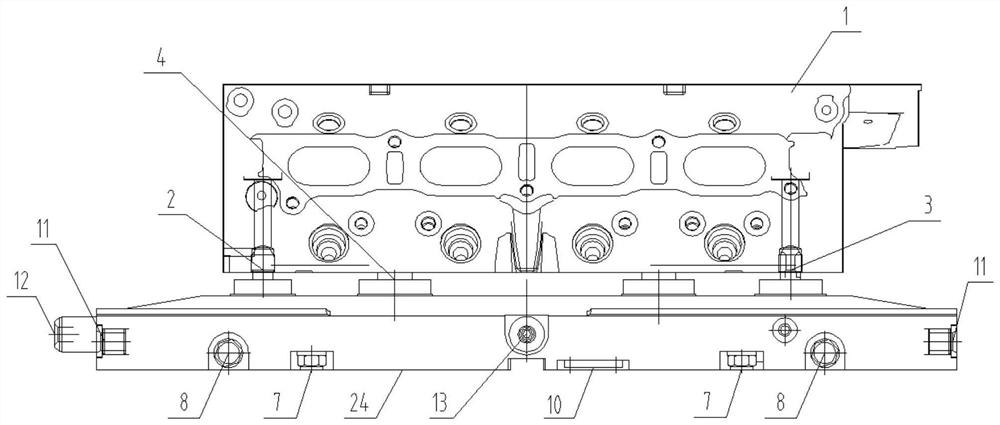
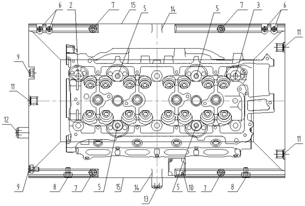
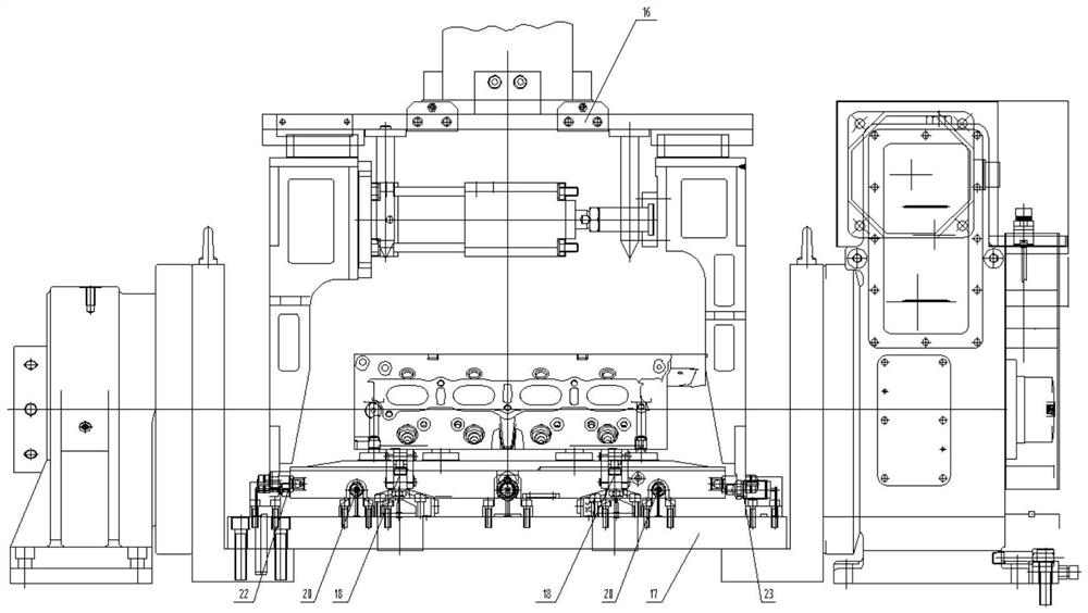
[0028] pass below Figure 1 to Figure 5 As well as listing some optional embodiments of the present invention, the technical solutions (including preferred technical solutions) of the present invention are further described in detail. Apparently, the described embodiments are only some of the embodiments of the present invention, not all of them. Based on the embodiments of the present invention, all other embodiments obtained by persons of ordinary skill in the art without creative efforts fall within the protection scope of the present invention.

[0029] In the description of the present invention, unless otherwise stated, the meaning of "plurality" is two or more; the terms "upper", "lower", "left", "right", "inner", "outer" , "front end", "rear end", "head", "tail", etc. indicate the orientation or positional relationship based on the orientation or positional relationship shown in the drawings, and are only for the convenience of describing the present invention and sim...


PUM


Abstract

The invention discloses an accompanying tray clamping device. A workpiece is connected with an equipment clamp through a tray body; a plurality of positioning blocks are arranged at the top of the tray body to form a positioning surface; positioning pins are arranged on the outer sides of the positioning blocks; the workpiece is positioned through the matching of the positioning surface and the positioning pins, and is fixed with the tray body through tightening bolts; the bottom of the tray body is provided with a plurality of bottom face abrasion-resistant positioning blocks matched with the equipment clamp, and two adjacent side faces of the tray body are provided with side face abrasion-resistant positioning blocks matched with the equipment clamp; the tray body and the equipment clamp form three-face positioning through the bottom face abrasion-resistant positioning blocks and the side face abrasion-resistant positioning blocks; and the two opposite side faces of the tray body are provided with a plurality of abrasion-resistant limiting holes and abrasion-resistant limiting faces matched with a workpiece moving device. The accompanying tray clamping device is simple in structure and low in cost, the situation that the size precision of a workpiece is affected due to workpiece positioning reference transformation is avoided, abrasion of holes in all faces of the aluminum alloy workpiece is avoided, the rejection rate of aluminum alloy workpiece finished products is reduced, and the machining efficiency of aluminum alloy workpieces is improved.

Description

technical field [0001] The invention belongs to the technical field of mechanical processing, and specifically refers to a workpiece accompanying pallet clamping device that can be used for automatic production line automatic conveyance, automatic loading and unloading, and repeated clamping and positioning. Background technique [0002] In the increasingly mature industrial automation production, especially in the field of mechanical processing, the machining accuracy of workpieces is getting higher and higher, and there are more and more types of workpieces in the same series, and the degree of automation is getting higher and higher. Robots or manipulators replace humans to complete There are more and more workpieces being loaded and unloaded. If only single-sequence workpiece processing is processed, the process is very simple and easy to implement. However, in the field of mechanical processing with increasingly fierce competition, in order to reduce costs and improve p...

Claims


Application Information

Patent Timeline
Patent Type & Authority Applications(China)
IPC IPC(8): B65G37/02B65D19/44B65D19/38B65D77/28
CPCB65G37/02B65D19/44B65D19/38B65D77/28B65D2519/00815
Inventor 杨孔华
Owner 东风设备制造有限公司
Learn More