
Self-early-warning high-heat-dissipation laser obstacle removing platform system

A technology with high heat dissipation and barrier removal, applied in lasers, laser parts, laser parts and other directions, it can solve the problems of long operation time, large safety hazards, and reduce the reliability of power grid power supply, so as to improve the service life and protect safety. Effect

Active Publication Date: 2021-10-29
深圳金伊尔科技有限公司 +1
View PDF0 Cites 1 Cited by
  • Summary
  • Abstract
  • Description
  • Claims
  • Application Information

AI Technical Summary

Problems solved by technology

The traditional treatment method requires line power outage or live work, but line power outage reduces the reliability of power grid power supply, increases the risk of regional power outage, and causes large economic losses and negative social impact. Relying on personnel or entering the high-voltage electric field, directly or indirectly contacting the charged body, removing falling objects, endangering trees, etc., there are high operational risks, great safety hazards, and long operation time
[0003] Therefore, a laser obstacle remover has been developed on the market. The laser obstacle remover uses the ground to emit controllable light to cut the foreign objects on the hanging wire at a long distance. However, when the laser obstacle remover is in use, the staff usually clean it After finishing this foreign object, immediately rush to the next foreign object hanging place on the line to work, but in this way, all equipment needs to be stored in a separate appliance, and then taken out for assembly when reaching the next foreign object hanging place, Not only makes it inconvenient for the staff to carry, but also reduces the work efficiency of the staff

Method used

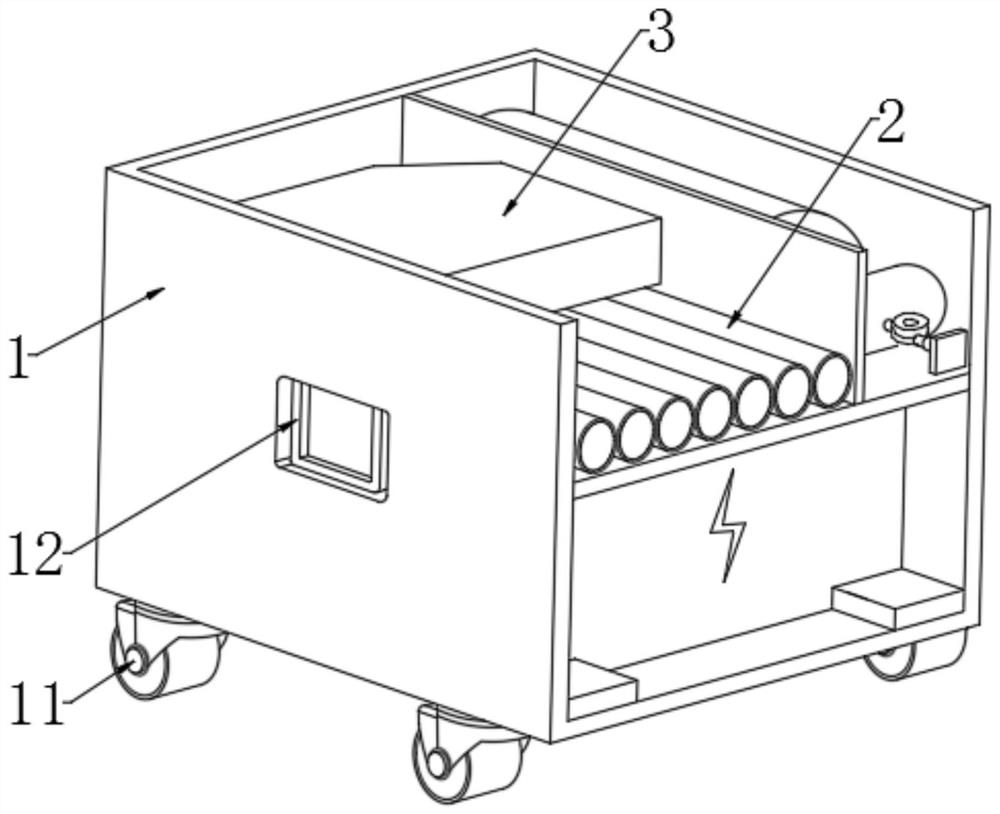
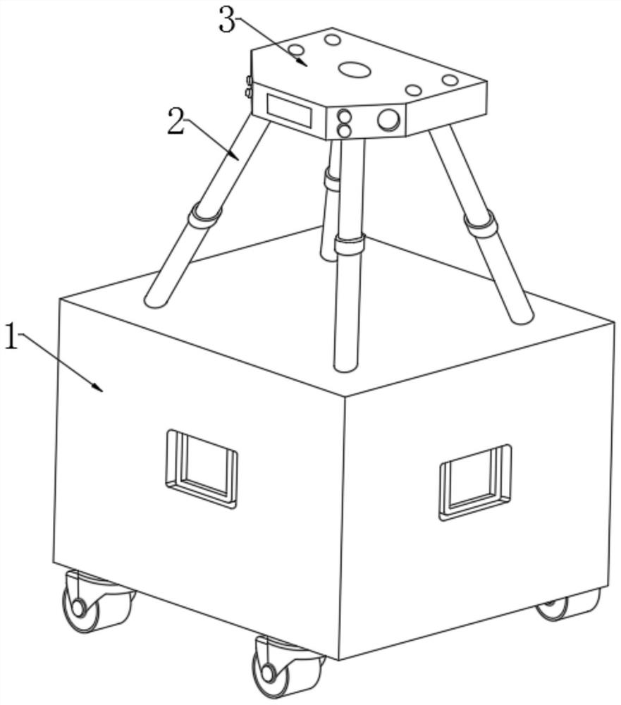
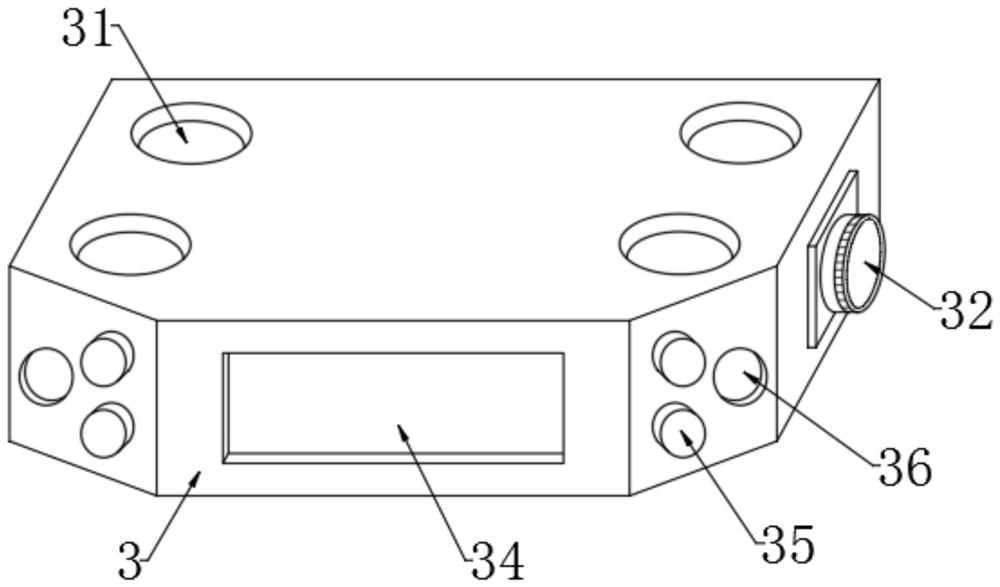

Image

  • Self-early-warning high-heat-dissipation laser obstacle removing platform system
  • Self-early-warning high-heat-dissipation laser obstacle removing platform system
  • Self-early-warning high-heat-dissipation laser obstacle removing platform system

Examples


Embodiment Construction

[0032] The technical solutions in the embodiments of the present invention will be clearly and completely described below in conjunction with the accompanying drawings in the embodiments of the present invention; obviously, the described embodiments are only some of the embodiments of the present invention, not all of them, based on The embodiments of the present invention and all other embodiments obtained by persons of ordinary skill in the art without making creative efforts belong to the protection scope of the present invention.

[0033] In the description of the present invention, it should be noted that the orientations or positional relationships indicated by the terms "upper", "lower", "inner", "outer", "top / bottom" etc. are based on the orientations shown in the drawings Or positional relationship is only for the convenience of describing the present invention and simplifying the description, but does not indicate or imply that the device or element referred to must h...


PUM


Abstract

The invention discloses a self-early-warning type high-heat-dissipation laser obstacle removing platform system which can analyze a supporting platform and the surrounding environment through a radar detection unit and an inclination angle sensing unit while a laser obstacle removing instrument works, and when a person or an object enters a fan-shaped detection area of the radar detection unit, the inclination angle sensing unit can detect whether the person, or when the inclination angle sensing unit detects that the supporting cradle head inclines by more than 30 degrees leftwards and rightwards, the output power supply of the battery can be cut off immediately, so that the laser transmitter stops working, the safety of personnel around the equipment is protected, and when the laser transmitting port works for a long time and is overheated, the temperature-sensing early-warning mechanism can spontaneously cool the laser emission port, and at the same time, the externally-colored bump indicates that the position is overheated and the equipment needs to be shut down for rest, so that the service life of the equipment can be effectively prolonged.

Description

technical field [0001] The invention relates to the technical field of laser application, more specifically, to a self-warning type high heat dissipation laser obstacle removal platform system. Background technique [0002] Overhead transmission lines have the characteristics of many points and wide areas, and the environment in which they are located is complex. The line trips are often caused by external force intrusion. The most common external force intrusion includes ribbons, advertising banners, agricultural plastic films, kites, tree barriers, and bird's nests. These foreign objects bring major safety hazards to the safe operation of transmission lines. Therefore, when these foreign objects are found, they should be removed in time to ensure that potential safety hazards are eliminated before the accident occurs. The traditional treatment method requires line power outage or live work, but line power outage reduces the reliability of power grid power supply, increase...

Claims


Application Information

Patent Timeline
Patent Type & Authority Applications(China)
IPC IPC(8): G01D21/02G01K1/02H02G1/02H02H5/12H01S3/04
CPCG01D21/02G01K1/02H02H5/12H02G1/02H01S3/0407
Inventor 胡宇轩王一名原瀚杰郑耀华曾彦超陈用生曾水悦
Owner 深圳金伊尔科技有限公司
Learn More