Flue gas measuring device

A measuring device and flue gas technology, which is applied to measuring devices, sampling devices, analyzing gas mixtures, etc., can solve the problems of insufficient flue gas mixing, limited length, excessive ammonia injection, etc., so as to prevent affecting the measurement accuracy and improve the accuracy. The effect of preventing ash blocking

Pending Publication Date: 2021-10-29
国能濮阳热电有限公司
View PDF0 Cites 2 Cited by
  • Summary
  • Abstract
  • Description
  • Claims
  • Application Information

AI Technical Summary

Problems solved by technology

Sampling probes will be used in the extraction analysis method. The existing sampling probes are single-point sampling probes, but the length of the straight pipe at the outlet of the SCR denitrification reactor is limited (the distance from the outlet of the SCR reactor to the inlet of the upper air preheater is less than 5 meters). In the flue with large cross-section and small straight section, which is prone to turbulence and turbulence, the flue gas is not mixed sufficiently, and the conventional single-point sampling may not be able to measure the representative NOx content value.
Although the multi-point sampling method has also appeared on the market, the effect is limited, and the amount of ammonia injection often exceeds the standard, and it cannot be put into the denitrification system for automatic sampling.
In addition, the high-temperature flue gas needs to be cooled during the dilution extraction method, but the high-temperature flue gas will form condensed water during the cooling process, and the dissolved pollutants in the flue gas will condense into water, which will affect the measurement results of the flue gas

Method used


Image

  • Flue gas measuring device
  • Flue gas measuring device
  • Flue gas measuring device

Examples


Embodiment Construction

[0026] The following will clearly and completely describe the technical solutions in the embodiments of the present invention with reference to the accompanying drawings in the embodiments of the present invention. Obviously, the described embodiments are only some, not all, embodiments of the present invention.

[0027] Examples of embodiments are shown in the drawings, wherein like or similar reference numerals denote like or similar elements or elements having same or similar functions throughout. The embodiments described below by referring to the figures are exemplary and are intended to explain the present invention and should not be construed as limiting the present invention.

[0028] In describing the present invention, it should be understood that the terms "center", "longitudinal", "transverse", "length", "width", "thickness", "upper", "lower", "front", " Back", "Left", "Right", "Vertical", "Horizontal", "Top", "Bottom", "Inner", "Outer", "Clockwise", "Counterclockw...


PUM


Abstract

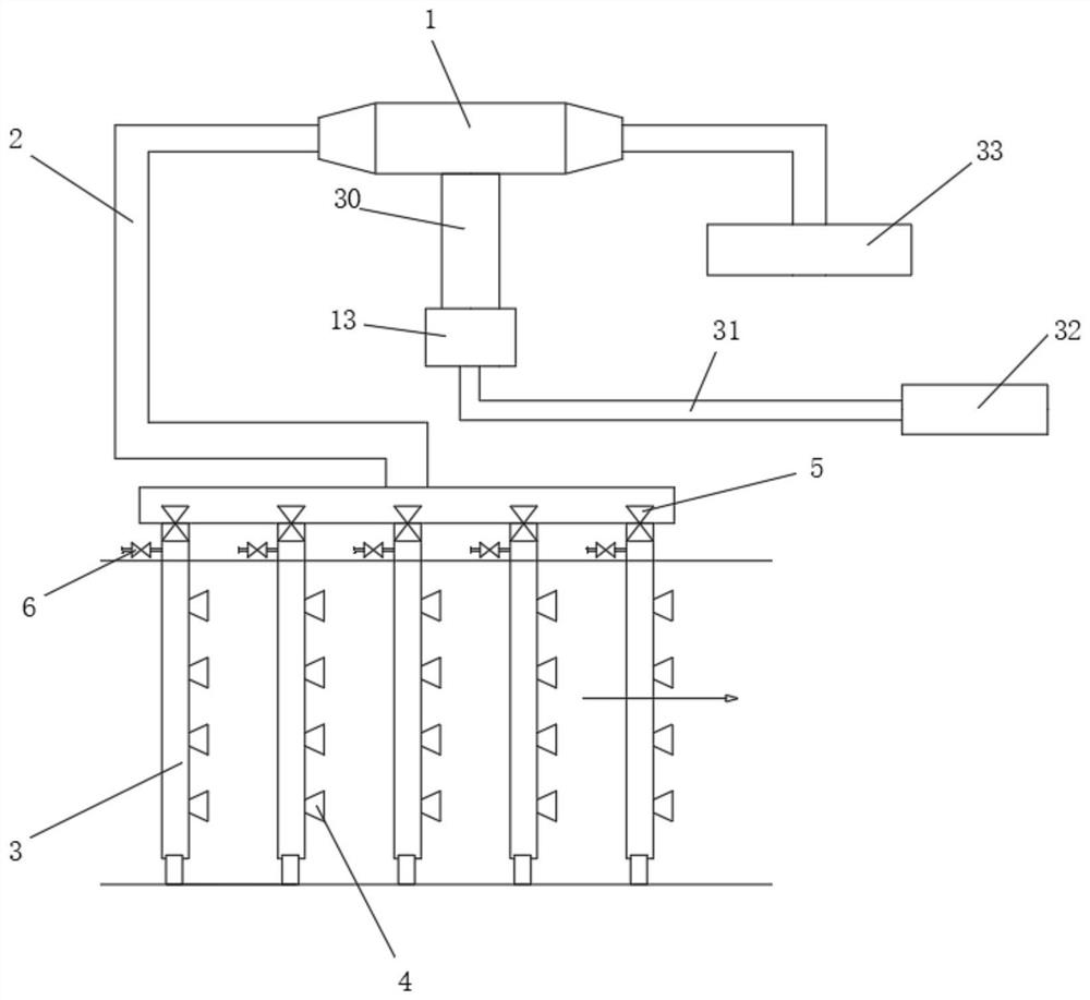
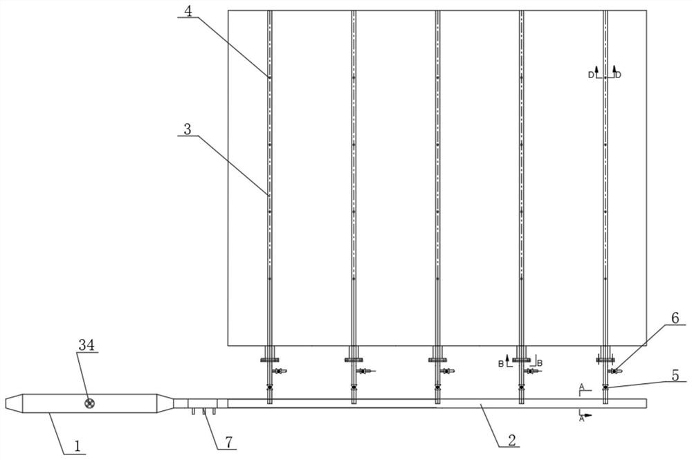
The invention discloses a flue gas measuring device which comprises a plurality of first sampling pipes distributed on the cross section of an outlet flue of a denitration device in a matrix mode, each first sampling pipe is provided with a plurality of trumpet-shaped sampling holes at equal intervals, all the first sampling pipes are jointly connected to a collecting pipe, one end of the collecting pipe is connected with a flow equalizing pipe, the middle part of the flow equalizing pipe is connected with a sampling pipe, the sampling pipe samples flue gas in the flow equalizing pipe and then conveys the flue gas into a flue gas pretreatment system through a composite sampling pipe, the flow equalizing pipe is communicated with an air pre-heater outlet steering chamber through a return pipe, and a dilution cooler is also connected between the collecting pipe and the flow equalizing pipe. The dilution cooler can divide flue gas into two parts, one part is diluted after being pre-cooled and then is further cooled, and the cooled and diluted gas is fully stirred and mixed with high-temperature flue gas in the heat tracing pipeline, so that the flue gas is fully mixed with the high-temperature flue gas in the heat tracing pipeline. The influence on the measurement precision caused by cooling nucleation or water vapor condensation into beads due to too low cooling temperature can be further prevented.

Description

technical field [0001] The invention relates to the technical field of flue gas sampling and detection, in particular to a flue gas measuring device. Background technique [0002] CEMS flue gas online continuous monitoring system is a high-tech product urgently needed in the national environmental protection field. It is mainly used for continuous online monitoring of the emission concentration and total emission of soot, sulfur dioxide and nitrogen oxides in flue gas. At present, there are two mainstream analysis techniques in the market, namely direct analysis method and extraction analysis method, and extraction analysis method is divided into complete extraction method and dilution extraction method. Sampling probes will be used in the extraction analysis method. The existing sampling probes are single-point sampling probes, but the length of the straight pipe at the outlet of the SCR denitrification reactor is limited (the distance from the outlet of the SCR reactor to ...

Claims


Application Information

Patent Timeline
Patent Type & Authority Applications(China)
IPC IPC(8): G01N1/24G01N33/00G01N15/00
CPCG01N1/24G01N33/0004G01N15/00
Inventor 王欣
Owner 国能濮阳热电有限公司
Why Eureka
Try Eureka