

Environment-friendly gas insulation ring main unit
A technology of gas insulation and ring main unit, which is applied in the direction of electrical components, high-voltage air circuit breakers, switchgear, etc., can solve the problems of high cost and complex structure, achieve good self-locking performance, increase the depth of switches, and improve the level of processing technology Effect
- Summary
- Abstract
- Description
- Claims
- Application Information
AI Technical Summary
Problems solved by technology
Method used
Image

Examples
Embodiment 1
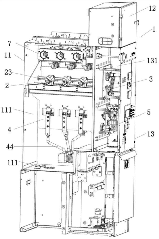
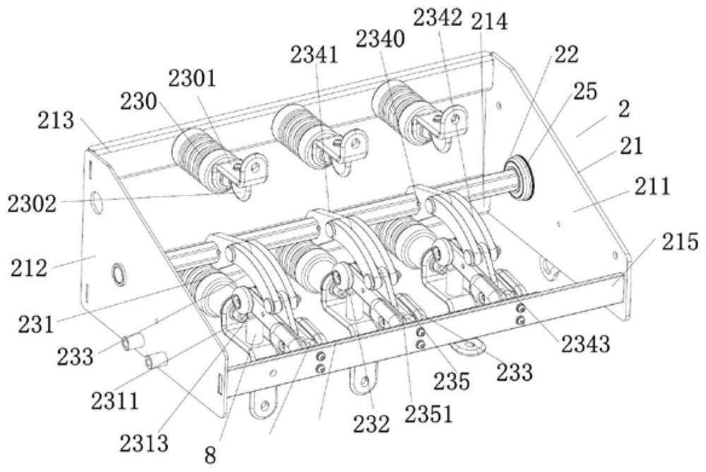
[0050] Such as Figure 1-21 As shown, an environment-friendly gas-insulated ring network cabinet includes a cabinet body 1, a three-position switch 2, a three-position mechanism 3, a circuit breaker main circuit 4 and a circuit breaker mechanism 5, a three-position switch 2, and a three-position mechanism 3. The main circuit 4 of the circuit breaker and the circuit breaker mechanism 5 are installed in the cabinet body 1. An interlock device 6 is connected between the three-station mechanism 3 and the circuit breaker mechanism 5 to prevent live operation. The three-station mechanism 3 and the three-station The switch 2 is connected with an indicating device 9 for displaying the state of the three stations.
[0051] The cabinet body 1 includes a gas box 11, an instrument room 12 and a cabinet frame 13. The cabinet frame 13 is equipped with a mechanism room 131 and a cable room 132. The gas box 11 is provided with an inflatable compartment 111, a circuit breaker mechanism 5 and a...
PUM
 Abstract
Description
Claims
Application Information