
Microwave ablation needle

A microwave ablation and external needle technology, applied in the field of microwave ablation needles, can solve the problems of ablation shape deviation, needle tip tissue carbonization, large energy loss of ablation needles, etc., and achieve the effect of improving clinical effect and reducing the possible effect of carbonization

Pending Publication Date: 2021-11-02
苏州锐诺医疗技术有限公司
View PDF0 Cites 2 Cited by
  • Summary
  • Abstract
  • Description
  • Claims
  • Application Information

AI Technical Summary

Problems solved by technology

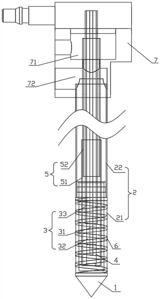
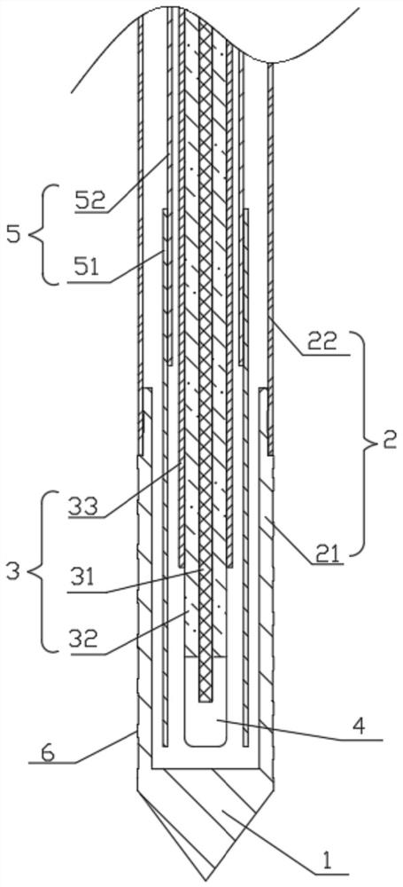
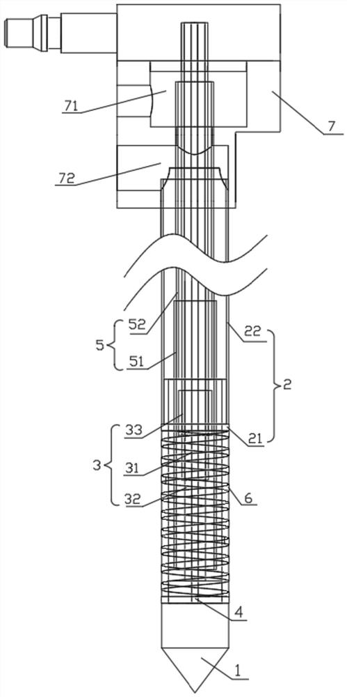
[0004] In order to solve the problems of large energy loss of existing ablation needles, ellipsoidal shape of ablation, and carbonization of tissue near the needle tip due to high temperature of the needle tip, the present invention innovatively provides a microwave ablation needle, which is provided with a spiral choke ring outside the outer needle tube. Suppress the electric field that escapes away from the needle tip, ensure that the electric field distribution presents a better spherical shape, and finally form a good spherical ablation shape; the setting of the water diversion pipe allows the cooling water to circulate and extend to the needle tip, and fully protect the needle tip and the outer needle tube. Cooling greatly reduces the possibility of carbonization of the ablation tissue around the needle tip and outer needle tube, improving the clinical effect

Method used


Image

  • Microwave ablation needle
  • Microwave ablation needle
  • Microwave ablation needle

Examples


Embodiment Construction

[0026] The microwave melting needle provided by the present invention will be described in detail with reference to the drawings.

[0027] like Figure 1-4 As shown, the present embodiment specifically discloses a microwave ablation needle, including a needle tip 1, an outer needle tube 2, a coaxial cable 3, a radiator 4, a water tube 5, a spiral choke loop 6, a coaxial cable 3, a water pipe 5 and the outer needle 2 from the inside and inwardly, between the pumping pipes 5 and the coaxial cable 3, there is a gap between the water pipe 5 and the outer needle 2. The radiator 4 is used to emission the microwave, and the coaxial cable 3 transmits the microwave generated by the microwave generator to the radiator 4, and the spiral choke ring 6 is used to suppress the electric field that is distinguished from the needle tip 1 direction. The voids between the vapor pipe 5 and the coaxial cable 3 form an inlet passage, and the gap between the water pipe 5 and the outer needle tube 2 forms ...


PUM


Abstract

The invention relates to a microwave ablation needle, which comprises a needle point, an outer needle tube, a coaxial cable, a radiator, a water conduit and a spiral choke ring, the coaxial cable, the water conduit and the outer needle tube are coaxially sleeved in sequence from inside to outside, gaps exist between the water conduit and the coaxial cable and between the water conduit and the outer needle tube, and the outer needle tube comprises a ceramic outer needle tube and a metal outer needle tube; the ceramic outer needle tube is fixedly connected with the needle point and the metal outer needle tube, the spiral choke ring is a metal film laid on the outer surface of the ceramic outer needle tube and is in conductive communication with the metal outer needle tube, and the radiator is fixedly connected or integrally formed with an inner conductor of the coaxial cable and located in a tube cavity, close to the needle point, of the ceramic outer needle tube. The water conduit comprises a PTEF water conduit and a metal water conduit, the PTEF water conduit and the metal water conduit are coaxially connected, the PTEF water conduit is partially or completely located in a pipe cavity of the ceramic outer needle pipe, and the metal water conduit is located in a pipe cavity of the metal outer needle pipe. The microwaves can be prevented from escaping to the far end of the needle tip, the needle tip is fully cooled, and clinical effects are improved.

Description

Technical field [0001] The present invention relates to the technical field of microwave treatment equipment, and more particularly, the present invention relates to a microwave ablation needle. Background technique [0002] In recent years, with the development of modern science and technology and induceology, domestic microwave tumor therapy has achieved effective breakthroughs, and microwave ablation has gradually become one of the important treatments of liver cancer. Microwave melting is to use modern imaging medicine (B / CT / MRI) as auxiliary puncture technology means, accurately thoroughly puncture the microwave ablation antennas to lesion tissue that requires ablation, and applies a certain amount of power and a certain frequency of lesions that need to be ablated. (Usually 900-2500 MHz) microwave energy. Using the polar molecule (water molecule, protein molecule, carbohydrate molecule) in the lesion to high speed oscillating, friction, collision to generate heat in the...

Claims


Application Information

Patent Timeline
Patent Type & Authority Applications(China)
IPC IPC(8): A61B18/18
CPCA61B18/1815A61B2018/1869A61B2018/00035A61B2018/00714
Inventor 刘晓伟张学武
Owner 苏州锐诺医疗技术有限公司
Learn More