
Central intelligent water supply system of printing machine and process of central intelligent water supply system

A technology for intelligent water supply and printing machines, applied to printing machines, rotary printing machines, lithographic rotary printing machines, etc., can solve the problems of wasting energy, poor water level control accuracy, and insufficient intelligence, and achieve the effect of convenient operation and simple structure

Pending Publication Date: 2021-11-02
广东兴艺数字印刷股份有限公司
View PDF16 Cites 0 Cited by
  • Summary
  • Abstract
  • Description
  • Claims
  • Application Information

AI Technical Summary

Problems solved by technology

[0003] At present, the water supply system used by the printing machine generally uses a water pump to directly supply water to the water tank. An overflow pipe is set on the water tank, and the excess water flows back from the overflow pipe to the water storage tank. The water level control accuracy is poor when the printing machine is in use. Sometimes it is intermittent, but the water pump is always on, which wastes energy. Therefore, it is necessary to manually control the start and stop of the water pump, which is not smart enough

Method used


Image

  • Central intelligent water supply system of printing machine and process of central intelligent water supply system
  • Central intelligent water supply system of printing machine and process of central intelligent water supply system
  • Central intelligent water supply system of printing machine and process of central intelligent water supply system

Examples


Embodiment approach

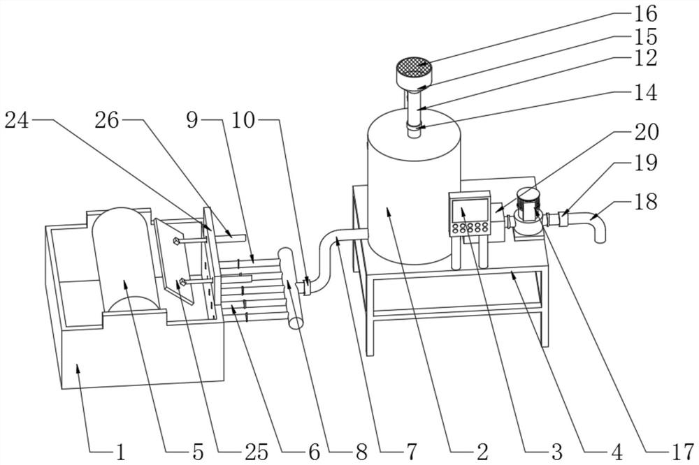
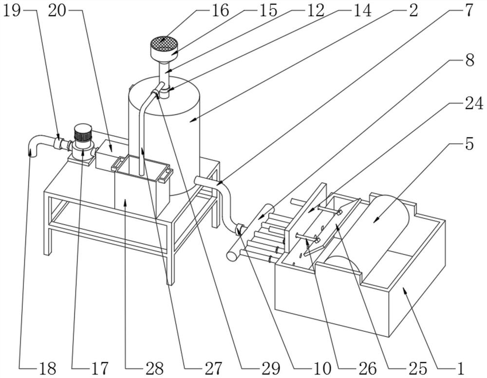
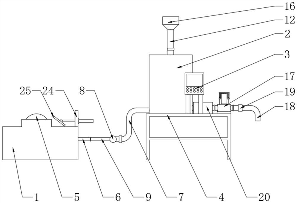
[0046] The embodiment is specifically: during the rotation of the water roller 5, the water attached to the water roller 5 splashes on the inner surface of the baffle 25, and flows back into the water tank 1 along the inner surface of the baffle 25, reducing the amount of water in the water tank 1. The situation of splashing to the outside occurs, which improves the utilization rate of water resources. The PLC controller 3 controls the electric telescopic rod 26 to work, pushes the baffle 25 to move, and adjusts the distance between the baffle 25 and the water roller 5, so that the baffle 25 It can effectively intercept the water splashed by the water roller 5 when it rotates, which improves the interception effect. This embodiment specifically solves the problem in the prior art that the water is easily splashed out of the water tank when the water roller rotates, resulting in the waste of water resources.

[0047] The present invention also includes: a process for the central...


PUM


Abstract

The invention discloses a central intelligent water supply system of a printing machine and a process of the central intelligent water supply system. The central intelligent water supply system comprises a water tank which is mounted on the printing machine, a water storage tank which is used for supplying water to the printing machine and a PLC (programmable logic controller) which is provided with an edited control program, water inlet pipes are mounted on the side wall of the water tank at equal intervals, a water conveying header pipe is connected to the bottom of the side wall of the water storage tank, a water distribution pipe is connected to the other end of the water conveying header pipe, water conveying branch pipes are fixedly arranged on the water distribution pipe at equal intervals, the water conveying branch pipes are connected with a water inlet pipe, a first water level sensor is installed on the lower portion of the inner side wall of the water storage tank, and a water pump is arranged on one side, away from the water conveying header pipe, of the water storage tank. The central intelligent water supply system is simple in structure, can automatically supplement water to the water storage tank and automatically supply water to the water tank through the water storage tank, does not need manual control, can keep the water level in the water tank unchanged all the time, can carry out filtration on water entering the water storage tank, improves the purity of the water, reduces the influence of impurities in the water on printing, and improves the printing quality.

Description

technical field [0001] The invention relates to the technical field of printing machines, in particular to a printing machine central intelligent water supply system and its technology. Background technique [0002] A printing press is a machine for printing text and images, and it is one of the most utilized equipment among all equipment in a printing factory. In the printing machine, in order to maintain the ink repellency of the part to be printed and the ink repellency of the non-graphic area of ​​the plate printing before inking, it is necessary to wet the plate with a dampening solution, and the water in the dampening solution occupies a large proportion. Therefore, in printing, water is very important, and how to smoothly supply water to the vicinity of the printing plate cylinder is very important. When the printing press is working, the water roller in the water tank rotates continuously to transfer the dampening liquid in the water tank to the water transfer rolle...

Claims


Application Information

Patent Timeline
Patent Type & Authority Applications(China)
IPC IPC(8): B41F7/32B41F33/00C02F9/06
CPCB41F7/32B41F33/0054C02F9/00C02F1/001C02F1/283C02F1/46
Inventor 黄真林文涛张治刚江坤华黄健明余泽林
Owner 广东兴艺数字印刷股份有限公司
Learn More